
Motor

a motor and motor technology, applied in the field of motors, can solve the problems of increasing the production cost of the motor, and inability to perform stable supply and demand of copper, so as to reduce the manufacturing cost, improve the motor productivity, and reduce the damage to the insulator generated when the motor is handled or assembled.

Active Publication Date: 2014-07-24
LG ELECTRONICS INC
View PDF13 Cites 8 Cited by
  • Summary
  • Abstract
  • Description
  • Claims
  • Application Information

AI Technical Summary

Benefits of technology

This patent aims to create a motor that uses less coil, reducing material costs and resistance, which improves motor performance and reduces the overall size of the motor. By doing so, the stator and rotor can be made more compact, resulting in a more efficient motor.

Problems solved by technology

However, such a copper material has a high raw price enough to increase the production cost of the motor.
Internationally, copper demand is rising suddenly such that stable supply and demand of copper cannot be performed frequently.
In this instance, there are concerns of high design costs and initial equipment investment costs.
However, in case of using such a method, the circular steel pieces generated in the stator core cannot be used and material waste might be caused.
Such a coupling boss is not necessarily configured to fix the stator to the tub.
This is because there is concern of damage to the coil caused by other objects placed nearby when the stator 100 is treated.
The appearance of the insulator having the fixing portions and the winding portions integrally formed with each other might be so complicated that it is not easy to fabricate such the insulator.
Moreover, when fabricating or treating the insulator, the winding portions are likely to have damage.
The frequency of winding the coil around the winding portions cannot help decreasing noticeably, because the minimum insulation distance has to be secured between each two neighboring coils.
As the thicknesses of the winding portions are increasing, the height of the coil cannot help increasing noticeably.
Accordingly, the height of the wound coil cannot help increasing remarkably.
There might be a problem of unnecessarily increased stator volume and another problem of unnecessarily long length of the coil.
Moreover, it is limited to increase the coil winding frequency.
The increase of the horizontal length of the coil results in increasing the material cost and weight of the motor as well as the resistance of the coil, such that ohmic loss could increase.
This can be directly connected with deterioration of motor efficiency.

Method used


Image

  • Motor
  • Motor
  • Motor

Examples


Embodiment Construction

[0114]In reference to the accompanying drawings, embodiments will be described in detail as follows.

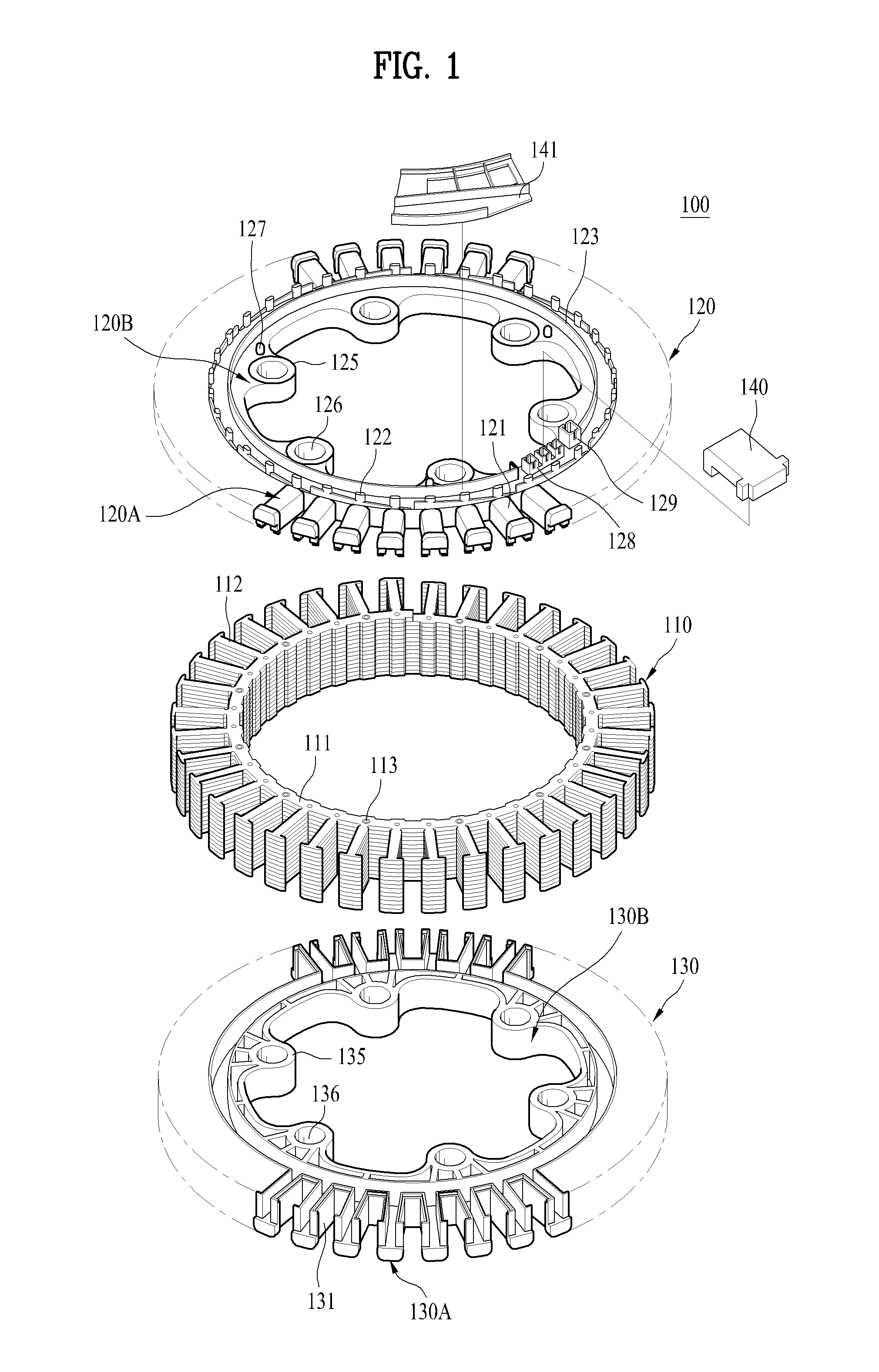
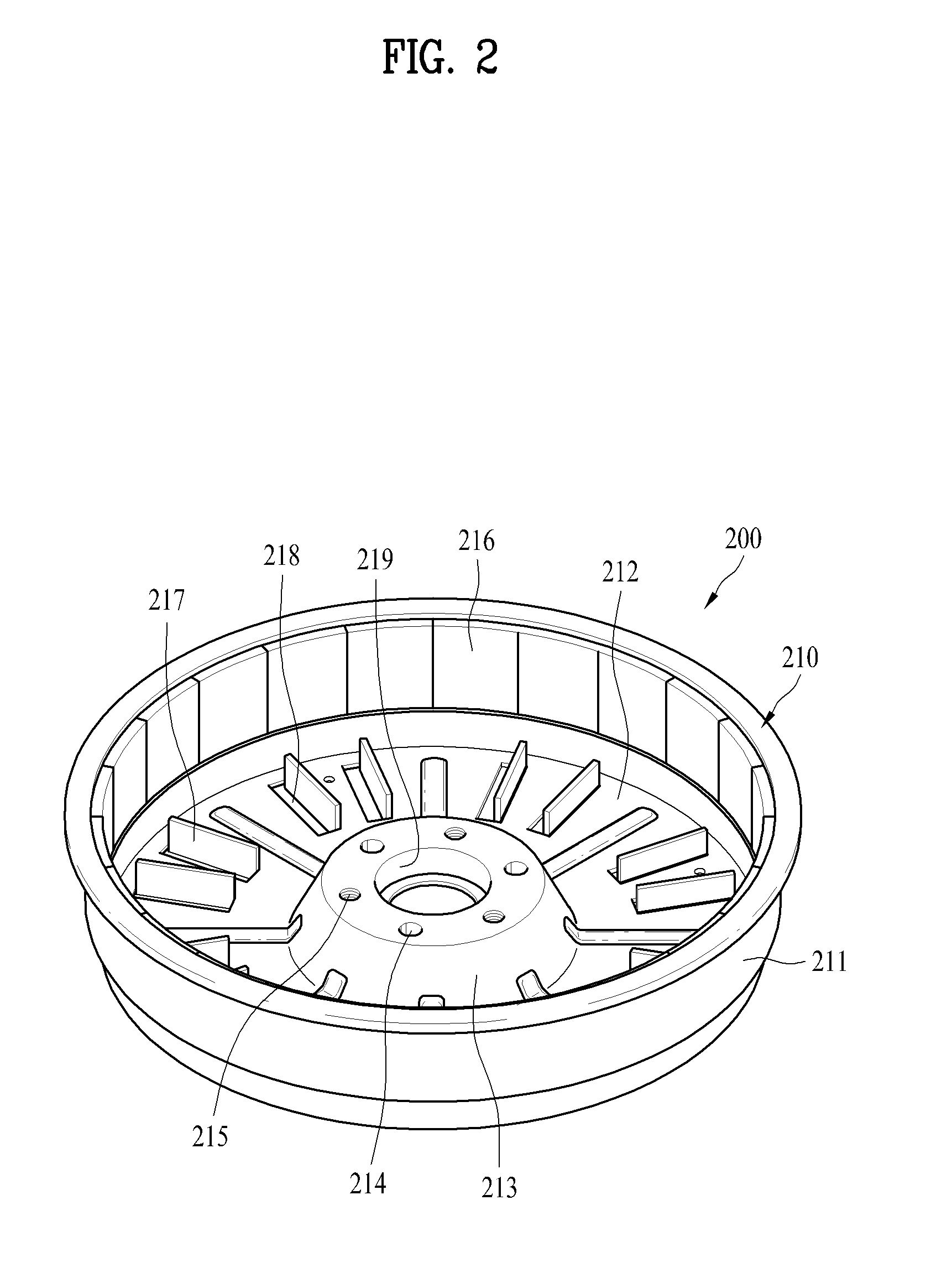
[0115]First of all, referring to FIGS. 1 and 2, the conventional stator core 110 and the rotor 200 can be applied to the motor according to embodiments identically or similarly. Together with that, some characteristics of the insulator 120 and 130 described, referring to FIG. 1, may be applied to the embodiments similarly. Accordingly, reference will now be made in detail to the specific embodiments of the present invention, examples of which are illustrated in the accompanying drawings. Wherever possible, the same reference numbers will be used throughout the drawings to refer to the same or like parts.

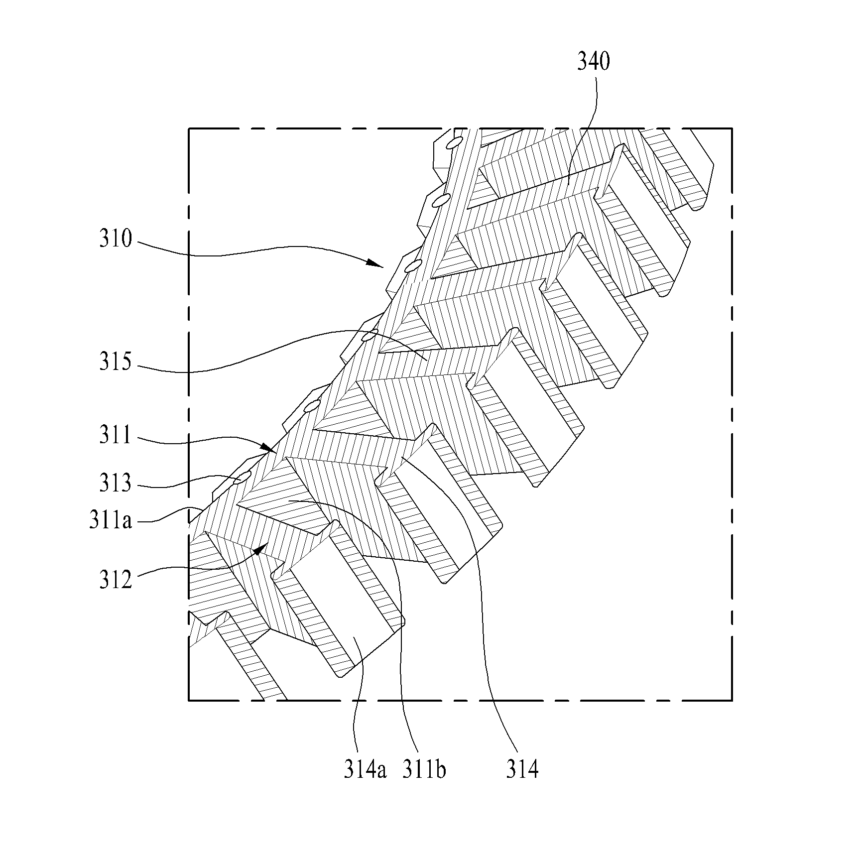
[0116]Referring to FIGS. 3 and 4, a stator provided in the motor according to one embodiment, specifically, a stator core will be described in detail as follows.

[0117]Different from the conventional stator core, the stator provided in the motor according to this embodiment may include ...


PUM


Abstract

There are disclosed a motor comprising a stator and a rotor rotary with respect to the stator, the stator comprising a stator core comprising a back yoke and a plurality of teeth projected from the back yoke 311 in a radial direction; an insulator provided in a predetermined portion in a radial direction with respect to the stator core to insulate the stator core from outside; and an insulation film formed from the other portion in the radial direction with respect to the stator core to the plurality of the teeth, to insulate stator core from the coil and the teeth, so as to reduce the manufacture price, with an easy manufacture process and an improved product reliability.

Description

[0001]Pursuant to 35 U.S.C. §119(a), this application claims the benefit of earlier filing date and right of priority to Korean Application No. 10-2013-0006155, filed on Jan. 18, 2013 the contents of which are hereby incorporated by reference herein in their entirety.BACKGROUND OF THE DISCLOSURE[0002]1. Field of the Disclosure[0003]The present invention relates to a motor, more particularly, to a motor that is able to reduce the manufacture price, with an easy manufacture process and improved product reliability.[0004]A motor according to embodiments may be a motor applied to a washing machine and examples of apparatuses the motor can be applied to are not limited to the washing machine.[0005]2. Discussion of the Related Art[0006]Generally, a motor is configured to transfer a rotational force of a rotor to a shaft for the shaft to drive a load. For example, the shaft is connected to a drum provided in a washing machine to drive the drum or it is connected to a fan provided in a refr...

Claims


Application Information

Patent Timeline
IPC IPC(8): H02K1/04
CPCH02K1/04H02K3/34H02K3/32H02K3/522B60J11/04
Inventor HA, HYUNHOKIM, SUNGJUNGJUNG, HYUNWOO
Owner LG ELECTRONICS INC
Learn More