Shock absorber with variable damping profile

Active Publication Date: 2014-07-24
KYNTEC
View PDF7 Cites 22 Cited by
  • Summary
  • Abstract
  • Description
  • Claims
  • Application Information

AI Technical Summary

Benefits of technology

The patent describes an energy absorption device that adjusts the rate of fluid flow through a shock tube by changing the alignment of holes and grooves in the device. This allows users to select which part of the device interfaces with the flow channel, resulting in different types of damping. The device also includes a cylinder end with two orifices and an end groove to facilitate fluid flow. The rotation of the shock tube relative to the external cylinder changes which part of the device interfaces with the flow channel, resulting in changes in damping. The technical effect of this invention is an energy absorption device that provides precise control over the rate of fluid flow and damping characteristics.

Problems solved by technology

Interaction of this degree is not found elsewhere in industry, where the highest degree of complexity in previous devices is limited to interaction between, for example, three parts.
Such rotation, thus, changes the dampening of the energy absorption device.

Method used


Image

  • Shock absorber with variable damping profile
  • Shock absorber with variable damping profile
  • Shock absorber with variable damping profile

Examples


Embodiment Construction

[0026]A description of example embodiments of the invention follows.

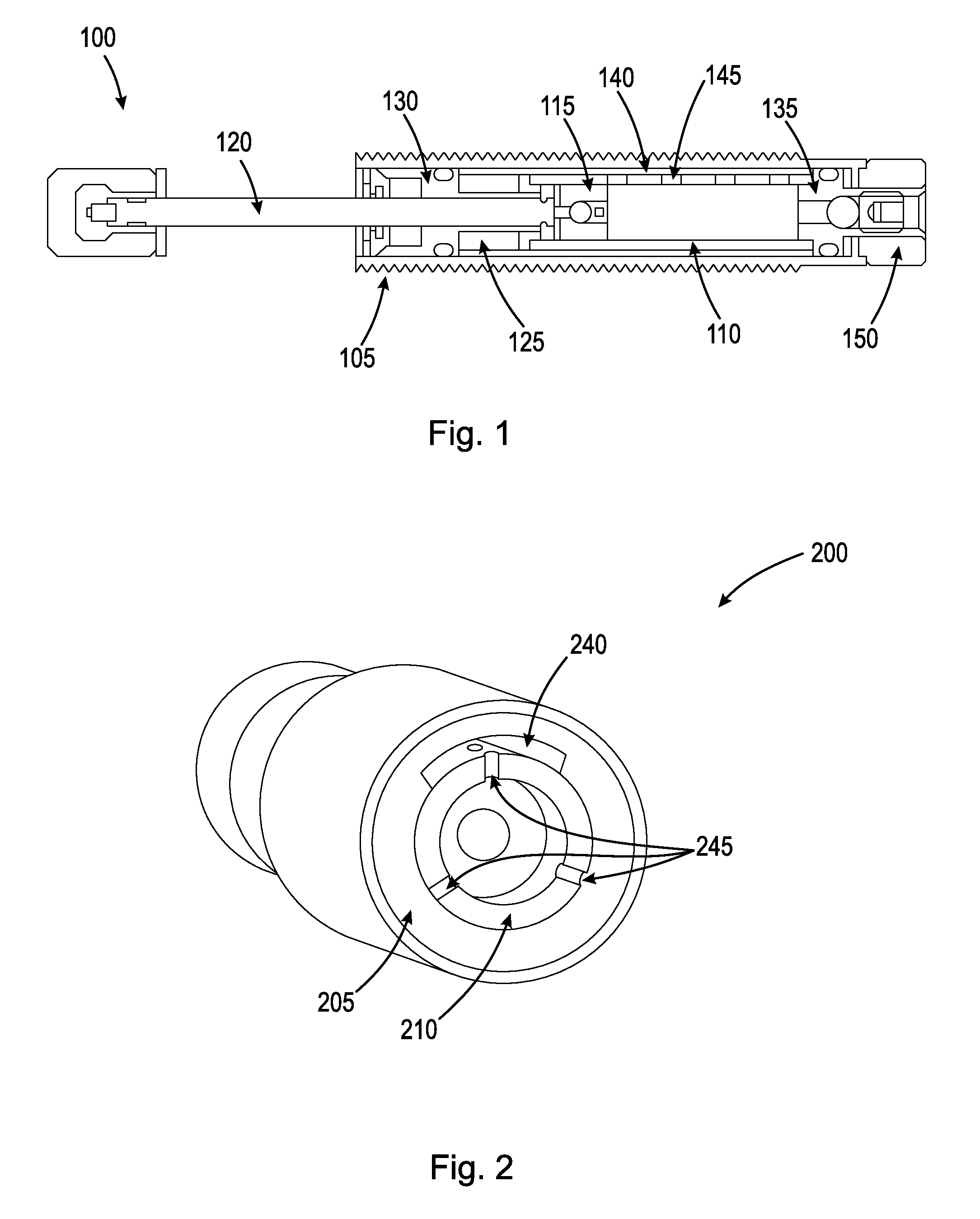
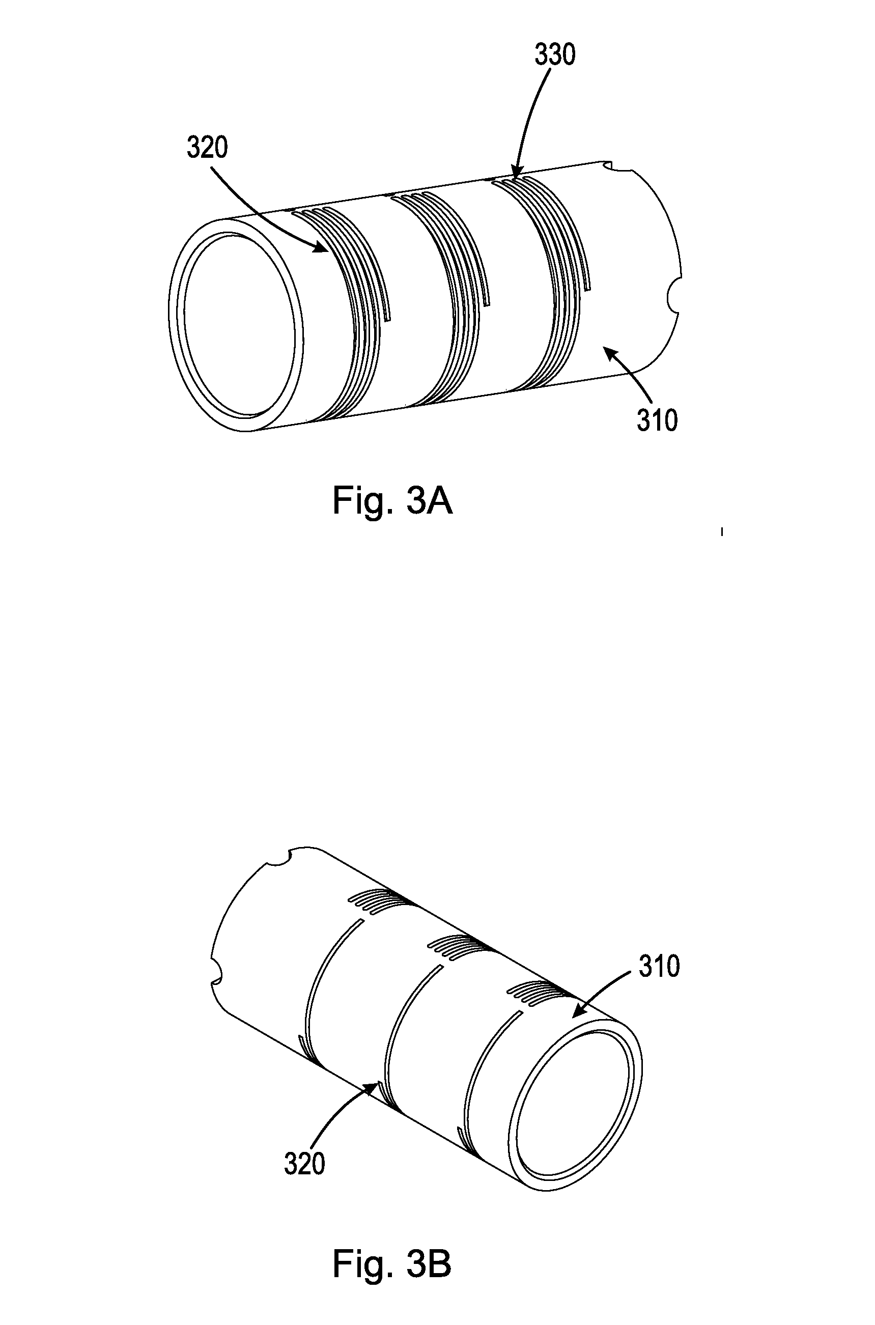
[0027]The device disclosed herein is a novel combination of interaction between features of various components (e.g., piston head, shock tube, cylinder end, external cylinder, and adjustment mechanism) within a single shock absorber. Designing and developing such parts to interact together and behave in a predictable way is neither obvious nor easy. Nonlinearities in flow, flow paths, interaction effects of multiple flow paths, and deliberate engineering of flow channels to be either active or inactive depending on customer orientation of the device has not been accomplished by others. The device disclosed herein combines into a single shock absorber the ability to select the most advantageous shock force vs. stroke damping profile for a given application, and to combine into a single device the ability to select damping characteristics previously unable to be combined in a single device. This allows a user of the s...


PUM


Abstract

Disclosed herein in an energy absorption device that incorporates a diverse range of uses within a single shock absorber. The disclosed energy absorption device is a novel combination of interaction between various components (e.g., piston head, shock tube, cylinder end, external cylinder, and adjustment mechanism) within a single shock absorber. When the components disclosed herein are considered together and designed as an interrelated assembly, the ability to incorporate such a diverse range of uses within a single device emerges. The ability to combine dashpot, square wave, progressive wave, and self-compensating damping in a single device is unprecedented, as is the ability to deliver sublinear damping force vs. input velocity performance in an adjustable device. The disclosed device allows a user to make simpler sizing calculations and decisions, and provides the user with the ability to adjust the shock absorber to a specific application, for example, with the turn of an adjustment knob.

Description

RELATED APPLICATIONS[0001]This application claims the benefit of U.S. Provisional Application No. 61 / 755,051, filed on Jan. 22, 2013, U.S. Provisional Application No. 61 / 827,900, filed on May 28, 2013, and U.S. Provisional Application No. 61 / 861,115, filed on Aug. 1, 2013. The entire teachings of the above applications are incorporated herein by reference.BACKGROUND OF THE INVENTION[0002]Most traditional non-adjustable shock absorbers can be designed to individually deliver progressive, square wave, dashpot, or self-compensating shock force vs. stroke profiles, but force a user to select between individual shock absorber units, each with a single damping profile. These traditional shock absorbers are, therefore, tuned to narrow performance bands within the specific shock force vs. stoke profile selected, and cannot compensate for changes in conditions of operation, including variations in load and impact velocity. Other traditional shock absorbers allow for adjustable damping only i...

Claims


Application Information

Patent Timeline
IPC IPC(8): F16F9/44F16F9/19
CPCF16F9/19F16F9/443F16F9/346F16F9/44F16F9/48F16F9/512
Inventor SPYCHE, JR., GERALD J.JOPP, ALLAN J.SCHOEN, JOSEPHTAYLOR, SCOTT J.
Owner KYNTEC
Why Eureka
Try Eureka