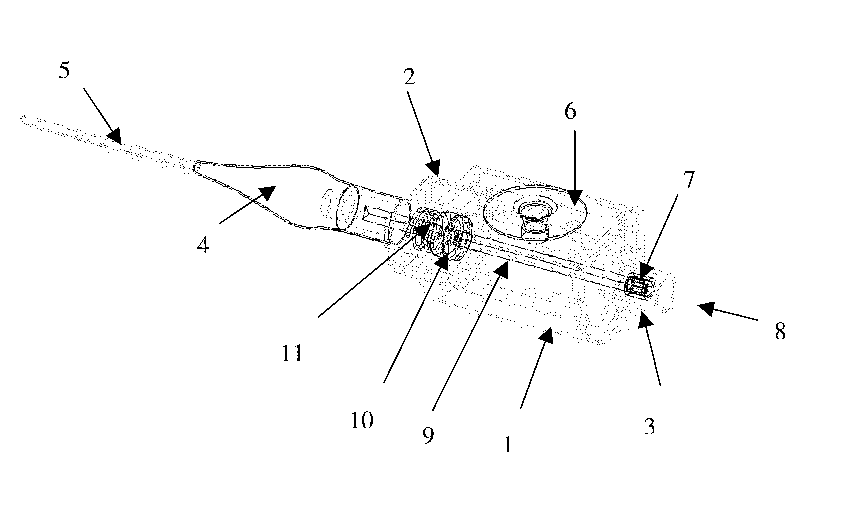
Pressure release means and placement indicator for inflatable catheter or respiratory gas supply retention means

a technology of inflatable catheters and indicators, which is applied in the direction of respirators, trachea tubes, wound drains, etc., can solve the problems of ett slipping or falling out, pneumonia and death, and the risk of local tissue damage to the patient, and achieves the effect of reducing the risk of infection, and improving the safety of patients

Inactive Publication Date: 2014-07-17
GILHULY TERENCE
View PDF2 Cites 18 Cited by
  • Summary
  • Abstract
  • Description
  • Claims
  • Application Information

AI Technical Summary

Benefits of technology

The invention is a device that allows for safe and proper inflation of balloons and cuffs on medical devices such as catheters and ETTs. It can be used as an adaptor that can be connected to these devices, or as a modification to the device itself. The invention includes a valve that prevents over-inflation or under-inflation, which can occur when using typical inflation methods. The technical effects of the invention include improved safety and reliability in the inflation process, as well as improved quality of the medical device.

Problems solved by technology

If the cuff is underinflated there is a risk of the ETT slipping or falling out, and / or for fluids, such as saliva, to enter the trachea possibly leading to pneumonia and death.
If the cuff is overinflated there is a risk of local tissue damage and further adverse events to the patient.
A related problem exists for insertion of other catheters that require inflation of a retention means for fixation (temporary or otherwise) in a body space.
If the insertion is correct but the inflation pressure is too low, the catheter may slip.
If the insertion is placed incorrectly and the retention means is inflated in a location that is too small to accommodate the inflated size, tissue damage may occur.
For example, over-inflating a balloon in a blood vessel could lead to rupture of the vessel.
Should the catheter not be inserted far enough and the balloon not enter the bladder, the balloon could be inflated within the patient's urethra resulting in pain if the patient is conscious, and if they are unconscious the overinflation may go unnoticed and the patient may also experience tissue damage due to the compression of the urethra.
Underinflation of the balloon for these catheters can lead to complications including loose catheters and spills.
However, previous mechanisms have been bulky and cumbersome, inefficient, complicated, disruptive of the user's routine practice, and costly to the point where these solutions are rarely seen and the problems of over- and underinflation still exist.

Method used


Image

  • Pressure release means and placement indicator for inflatable catheter or respiratory gas supply retention means
  • Pressure release means and placement indicator for inflatable catheter or respiratory gas supply retention means
  • Pressure release means and placement indicator for inflatable catheter or respiratory gas supply retention means

Examples


Embodiment Construction

[0028]One embodiment of the invention as an adaptor to provide inflation pressure control to an ETT or other catheter with inflatable retention means will now be described with reference to FIGS. 1 to 3.

[0029]In FIG. 1, the adaptor is shown in a perspective view and in FIG. 2, the adaptor is shown in a side view. The adaptor as shown is comprised of a main body 31, valve 36 and fluid supply interface cap 38.

[0030]Main body 31 has distal and proximal ends with the distal end having the ETT or catheter interface 32 and with the proximal end connecting to the fluid supply interface cap 38. Main body 31 has a passage to allow fluid to move through main body 31 between and through ETT or catheter interface 32 and interface cap 38. Joined to main body 31 is valve 36, which in FIGS. 1 to 3 is drawn as an umbrella valve that joins to main body 31 preferably on an external surface. Main body 31 (and main body 1 in FIGS. 4 to 6) can be cheaply manufactured using plastics and can be dyed to ha...


PUM


Abstract

Under- and overinflation of retention balloons and cuffs for catheters including Foley catheters, and for endotracheal tubes, tracheostomy tubes, laryngeal mask airways and similar devices is correlated with hospital acquired infections and with patient injury. In this patent, a solution that correctly inflates inflatable retention devices is taught, whereby a pressure release means is incorporated into the inflation pathway from the fluid input syringe to the retention means while inflating. This pressure release means can be set to open at or near the optimal fluid pressure so that overinflation can be prevented by releasing any pressure above the optimal pressure and underinflation can be prevented by a user pressurizing the cuff until the valve is noticed to open. As well, observation of fluid leaked through the pressure relief means can indicate misplacement of the retention means, allowing the user to reposition it before patient injury occurs. The invention is presented as a standalone part and in a format whereby the invention is integrated into existing airway cuff inflation designs.

Description

CROSS-REFERENCE TO RELATED APPLICATIONS[0001]The present application claims priority from U.S. provisional patent application Ser. No. 61 / 586,460 filed Jan. 13, 2011.STATEMENT REGARDING FEDERALLY SPONSORED RESEARCH OR DEVELOPMENT[0002]Not Applicable.REFERENCE TO SEQUENCE LISTING, A TABLE, OR A COMPUTER PROGRAM LISTING COMPACT DISC APPENDIX[0003]Not Applicable.BACKGROUND OF THE INVENTION[0004]Endotracheal tubes (ETT), tracheostomy tubes, laryngeal mask airways (LMAs) and similar devices are employed to provide respiration to patients in hospital settings when undergoing procedures or recovering or otherwise are unable to breathe. A typical ETT—such as the Mallinckrodt Hi-Lo Cuffed Tracheal Tube—comprises a tube to act as an airway, a cuff to secure the airway (a “retention means”), an inflation line to that cuff, a pilot balloon to assess pressure in the cuff, and an injection port with a one-way non-return valve to allow injection of fluid—typically air, water or saline—into the cuf...

Claims


Application Information

Patent Timeline
Patent Type & Authority Applications(United States)
IPC IPC(8): A61M16/04A61M25/00
CPCA61M25/0017A61M16/044A61M16/0434A61M16/0409A61M16/209
Inventor GILHULY, TERENCE
Owner GILHULY TERENCE
Why Eureka
Try Eureka