Discharge lamp lighting device, discharge lamp lighting method, and projector

a discharge lamp and lighting device technology, applied in the direction of light sources, electrical devices, instruments, etc., can solve the problems of discharge lamp blacking discharge lamp illuminance change, etc., to achieve the effect of reducing the occurrence of overshoot and undershoo

Active Publication Date: 2014-07-10
SEIKO EPSON CORP
View PDF13 Cites 1 Cited by
  • Summary
  • Abstract
  • Description
  • Claims
  • Application Information

AI Technical Summary

Benefits of technology

[0012]An advantage of some aspects of the invention is that a discharge lamp lighting device and a discharge lamp lighting method in which lighting control of a discharge lamp can be properly carried out while the influence of the occurrence of overshoot and undershoot is restrained and a projector having such a discharge lamp lighting device are provided.

Problems solved by technology

The occurrence of overshoot and undershoot causes change in illuminance of the discharge lamp and damage to the electrodes of the discharge lamp or the like.
Specifically, overheating of the electrodes of the discharge lamp due to the occurrence of overshoot and undershoot causes evaporation of tungsten forming the electrodes and may cause blacking of the discharge lamp.
Also, if vibration due to the occurrence of overshoot and undershoot is transmitted to the electrodes of the discharge lamp, it may cause breakdown of electrode coils.
Such damage due to the occurrence of overshoot and undershoot happens a greater number of times as the drive frequency of the discharge lamp becomes higher, and the damage is greater as the drive power (current, voltage) supplied to the discharge lamp is higher.
However, each of such traditional overshoot restraining methods lowers the responsiveness of the control unit to the drive waveform.
If the occurrence of overshoot is restrained excessively, the waveform of the drive current and the drive power or the like cannot be controlled accurately.
In such a case, a projected image from a projector may flicker because of change in illuminance of the discharge lamp.
Particularly, this phenomenon depends on the drive frequency of the discharge lamp and becomes more difficult to control as the frequency becomes higher.

Method used


Image

  • Discharge lamp lighting device, discharge lamp lighting method, and projector
  • Discharge lamp lighting device, discharge lamp lighting method, and projector
  • Discharge lamp lighting device, discharge lamp lighting method, and projector

Examples


Embodiment Construction

[0050]Hereinafter, an embodiment of the invention will be described in detail with reference to the drawings.

[0051]The drawings described below may show an enlarged view of a characteristic portion in order to facilitate understanding. Dimensional proportions of individual components may not be the same as the actual dimensional proportions thereof.

Projector

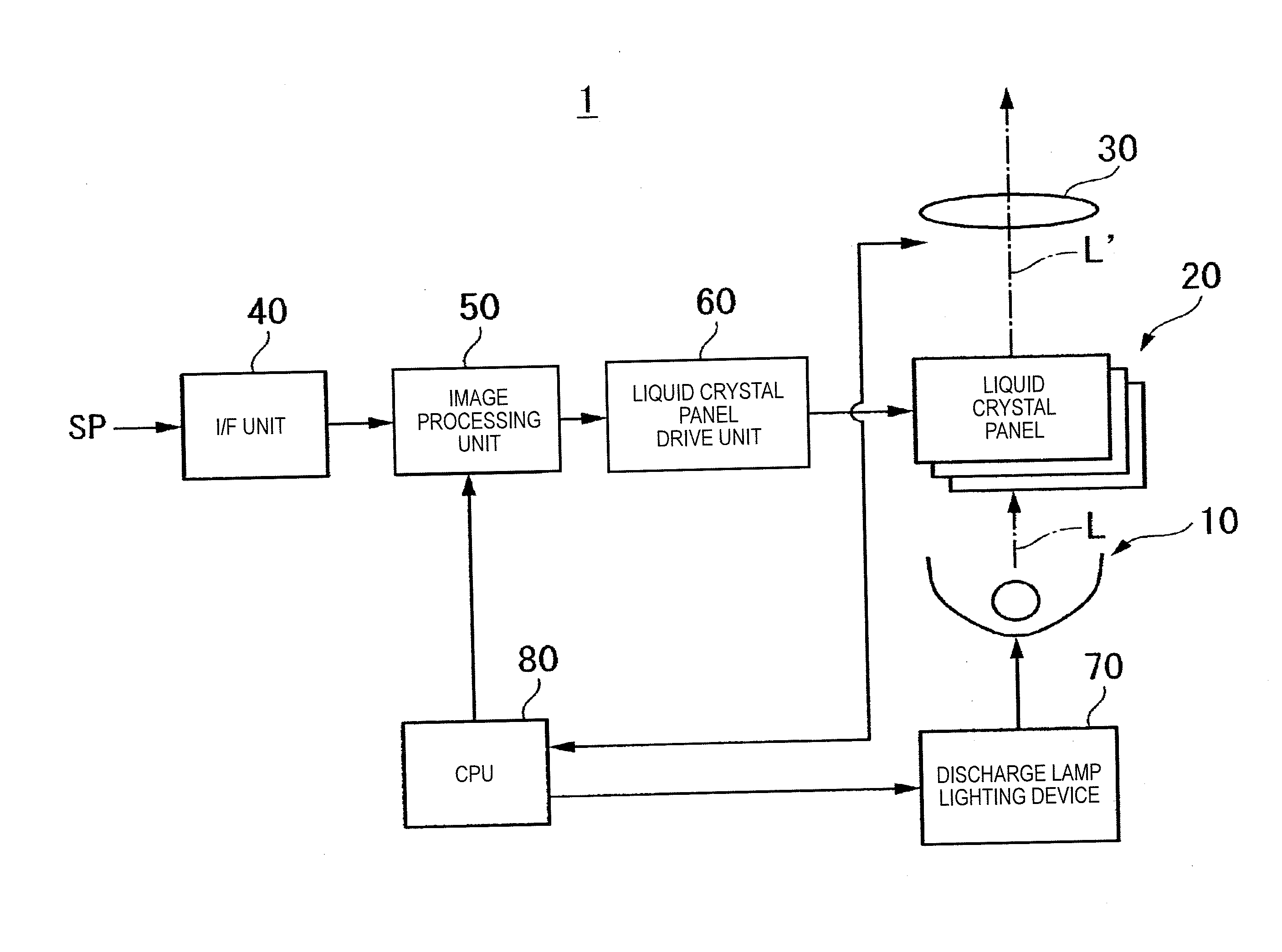
[0052]FIG. 1 is a block diagram showing a configuration example of a projector 1 according to this embodiment.

[0053]As shown in FIG. 1, this projector 1 schematically includes a discharge lamp (light source) 10 that casts illumination light L, a liquid crystal panel (light modulator) 20 that modulates the illumination light L according to image data and thus forms image light L′, and a projection system 30 that projects the image light L′ onto a screen (not shown).

[0054]In this embodiment, the case where an ultrahigh pressure mercury lamp utilizing arc discharge is used as the discharge lamp 10 is illustrated. However, the discha...


PUM


Abstract

A discharge lamp lighting method for controlling lighting of a discharge lamp includes varying an amount of generation (current value) of overshoot and undershoot generated in a waveform of a drive current that is applied when driving the discharge lamp, according to a magnitude of drive power supplied to the discharge lamp and a drive mode.

Description

BACKGROUND[0001]1. Technical Field[0002]The present invention relates to a discharge lamp lighting device, a discharge lamp lighting method, and a projector.[0003]2. Related Art[0004]Traditionally, as a light source for projector, for example, a discharge lamp such as an ultrahigh pressure mercury lamp, metal halide lamp or xenon lamp is used.[0005]By the way, in a discharge lamp lighting device that controls lighting of such a discharge lamp, overshoot and undershoot may occur in the waveform of a drive current that is applied when the discharge lamp is lit.[0006]Overshoot and undershoot are a phenomenon in which a higher current than expected flows temporarily between the electrodes of the discharge lamp, due to causes such as the circuit configuration of the discharge lamp lighting device, and in which every time the polarity of the drive current supplied to the discharge lamp is switched, the waveform of the drive current exceeds a base line that provides a stationary value, at ...

Claims


Application Information

Patent Timeline
Patent Type & Authority Applications(United States)
IPC IPC(8): H05B41/36
CPCH05B41/36H05B41/2882H05B41/2928
Inventor NAKAGOMI, YOICHITERASHIMA, TETSUO
Owner SEIKO EPSON CORP
Why Eureka
Try Eureka