Zoomable beamspreader with matched optical surfaces for non-imaging illumination applications

a beamspreader and optical surface technology, applied in lighting applications, lighting and heating apparatus, instruments, etc., can solve the problems of large system and many inches of travel

Inactive Publication Date: 2010-04-20
SIGNIFY NORTH AMERICA CORP
View PDF35 Cites 1 Cited by
  • Summary
  • Abstract
  • Description
  • Claims
  • Application Information

AI Technical Summary

Benefits of technology

[0009]The present invention provides a solid-state apparatus which is economically made, is scalable to large diameters yet operates over a short distance along the optical axis of a luminaire to control the distribution of light energy in non-imaging illumination applications.

Problems solved by technology

Such a system is quite large and requires many inches of travel for the lamp and reflector combination along the optical axis of the lens.

Method used


Image

  • Zoomable beamspreader with matched optical surfaces for non-imaging illumination applications
  • Zoomable beamspreader with matched optical surfaces for non-imaging illumination applications
  • Zoomable beamspreader with matched optical surfaces for non-imaging illumination applications

Examples


Embodiment Construction

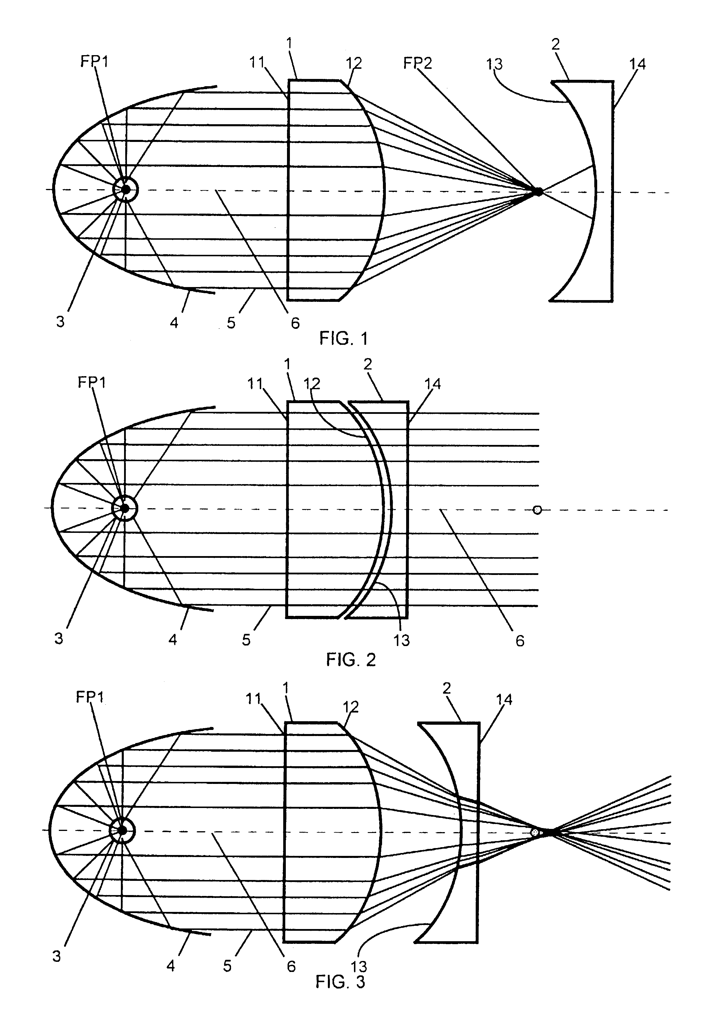
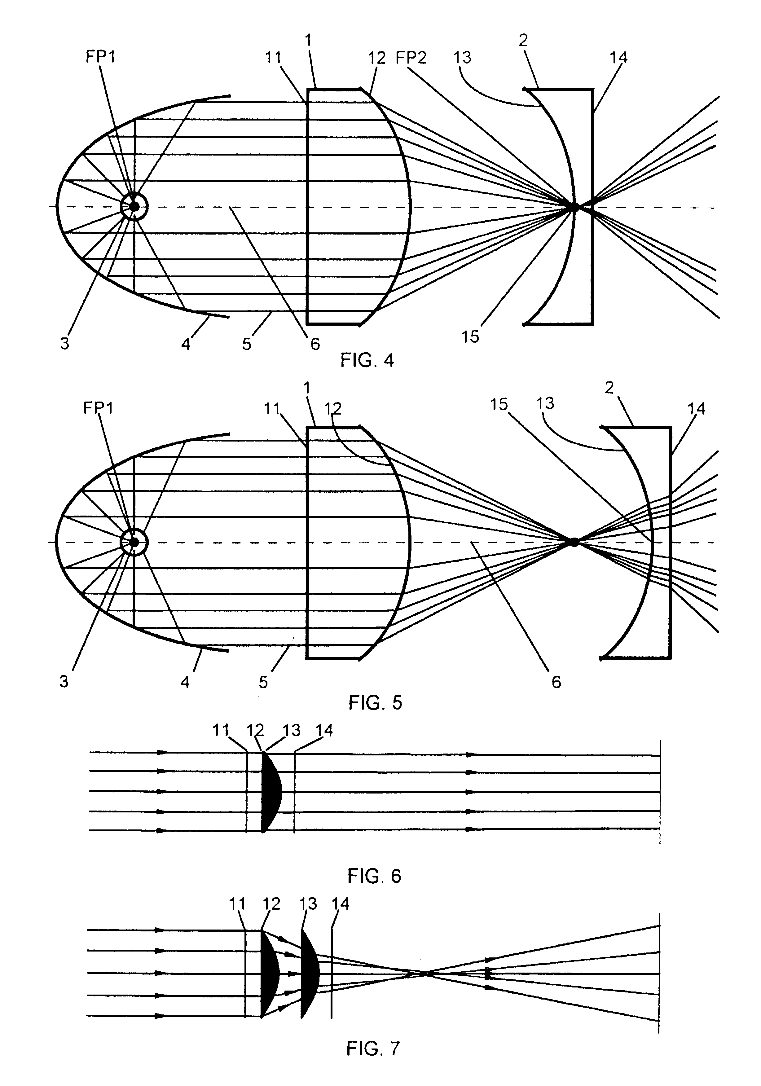
[0018]The operative concepts of an illumination optical system according to the present invention are described with reference to FIGS. 1-5. A first, plano-convex, lens 1 and a second, plano-concave, lens 2 are mounted coaxially with a lamp 3 and a reflector 4 forming a light beam 5 having an optical axis 6. The reflector is preferably parabolic and the lamp is preferably located at or near the focus FP1 of the parabola so that the resultant light beam is substantially collimated. Practically, however, the light beam will have a small angle of divergence of perhaps four or five degrees. The light beam is incident upon the planar surface 11 of the first lens and is refracted when passing through the convex surface thereof. The convex surface 12 of the first lens has a positive optical power and faces towards the concave surface 13 of the second lens, which has a negative optical power, and the two curved surfaces have matching shapes with equal but opposite optical powers. The shape ...


PUM


Abstract

A zoomable light beam spreader comprising first and second multiple-lens arrays includes a plurality of plano-convex lenses in correspondence with a plurality of plano-concave lenses having matched, curved optical surfaces. In a zero-power state, the two multiple-lens arrays are very closely spaced so that the matched convex and concave surfaces effectively cancel each other optically but, as the two arrays are separated coaxially along the axis of a light beam, beam divergence angle increases as a function of the distance of separation. A large amount of beam divergence is obtained when the curved surfaces of the plano-concave lenses of the second array are positioned beyond the focus points of the plano-convex lenses of the first array.

Description

FIELD OF THE INVENTION[0001]The present invention relates to lighting instruments, and especially to devices and apparatus for controlling the distribution of light energy in non-imaging illumination applications.DESCRIPTION OF RELATED ART[0002]Four qualities of lighting as described by Stanley McCandless in his book “A Method of Lighting the Stage” are intensity, color, distribution, and movement. Whereas intensity and color may be said to refer to attributes of particular light beams, distribution refers to the arrangement of light sources about the stage and the directions in which they are aimed. Intensity, color, and distribution are primary qualities, whereas movement is emergent from changes in the primary qualities. Movement in this sense occurs as the condition of the other three qualities changes over time. A simple adjustment of intensity results in movement. No change in any of the other three qualities can occur without resulting in movement, and movement cannot occur w...

Claims


Application Information

Patent Timeline
Patent Type & Authority Patents(United States)
IPC IPC(8): G02B27/10G02B17/08F21S2/00F21S10/00F21V5/00F21V13/00F21V14/00F21W131/406F21Y101/00G02B3/00G02B15/14G02B27/00
CPCG02B26/0875G02B27/0961G02B3/0056G02B3/0062G02B3/0075G02B15/14
Inventor HOUGH, THOMAS A.
Owner SIGNIFY NORTH AMERICA CORP
Why Eureka
Try Eureka