
Signal communication system and method for a vehicle system

a communication system and vehicle technology, applied in the field of signal communication systems and methods for vehicle systems, can solve the problems of long delay before the vehicle system resumes, communication transmitted between vehicles can congest the available bandwidth used to transmit signals, and the message cannot be received

Inactive Publication Date: 2014-07-03
GENERAL ELECTRIC CO
View PDF1 Cites 10 Cited by
  • Summary
  • Abstract
  • Description
  • Claims
  • Application Information

AI Technical Summary

Benefits of technology

The patent describes a communication system for a vehicle system that includes multiple vehicles that are connected together and can travel along a route. The system includes a controller that directs a wireless communication device to switch between an off-board communication mode and an onboard communication mode. The wireless communication device can receive remote data signals when in off-board mode and communicate local data signals when in onboard mode. The controller can also control the movement of the vehicle system based on the received remote data signals and the local data signals. Additionally, the patent describes a radio that can communicate with both onboard and remote devices using different frequency bandwidths. The technical effects of this patent include improved communication capabilities and the ability to control vehicle movement based on external data signals.

Problems solved by technology

The potentially large number of local communications transmitted between vehicles can congest the available bandwidth used to transmit the signals.
Signals may get lost in the transmission, resulting in non-receipt of the contained message.
A shut-down caused by non-receipt of a local signal could result in a long delay before the vehicle system resumes its route.

Method used


Image

  • Signal communication system and method for a vehicle system
  • Signal communication system and method for a vehicle system
  • Signal communication system and method for a vehicle system

Examples


Embodiment Construction

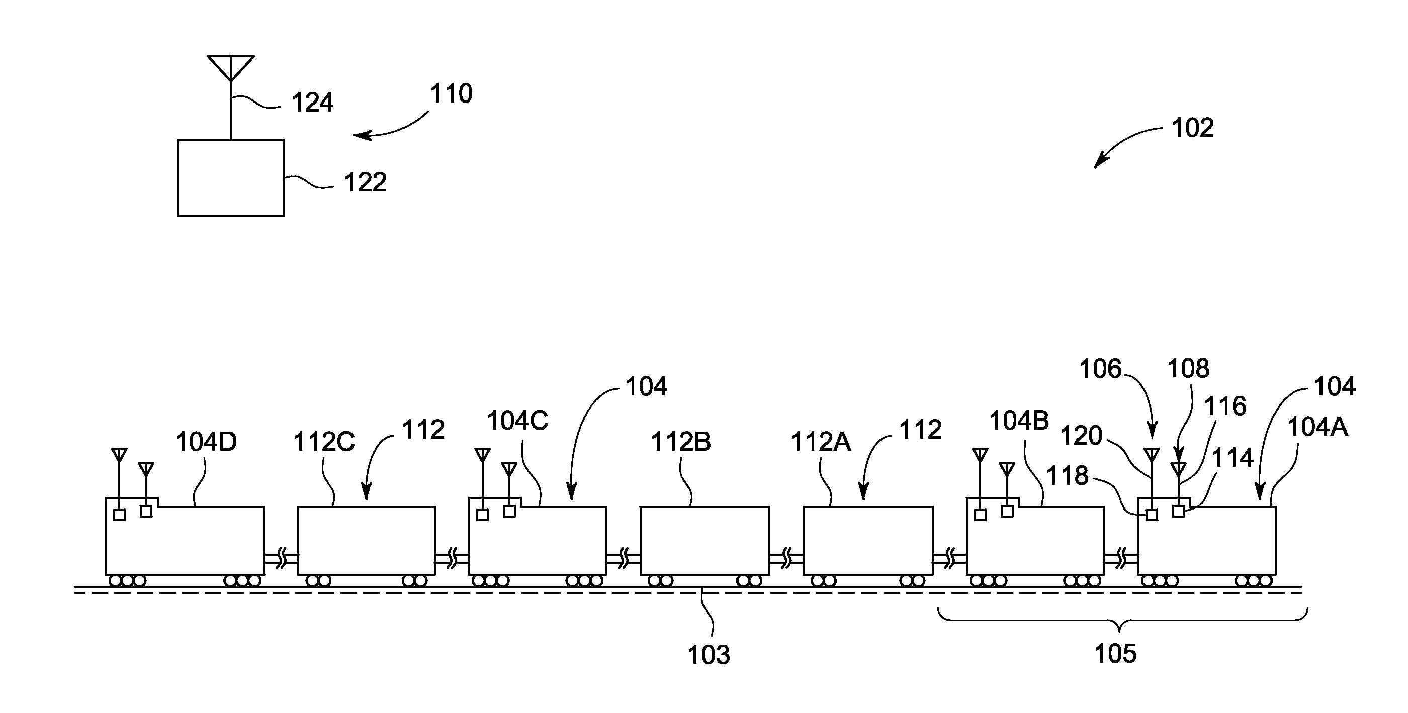
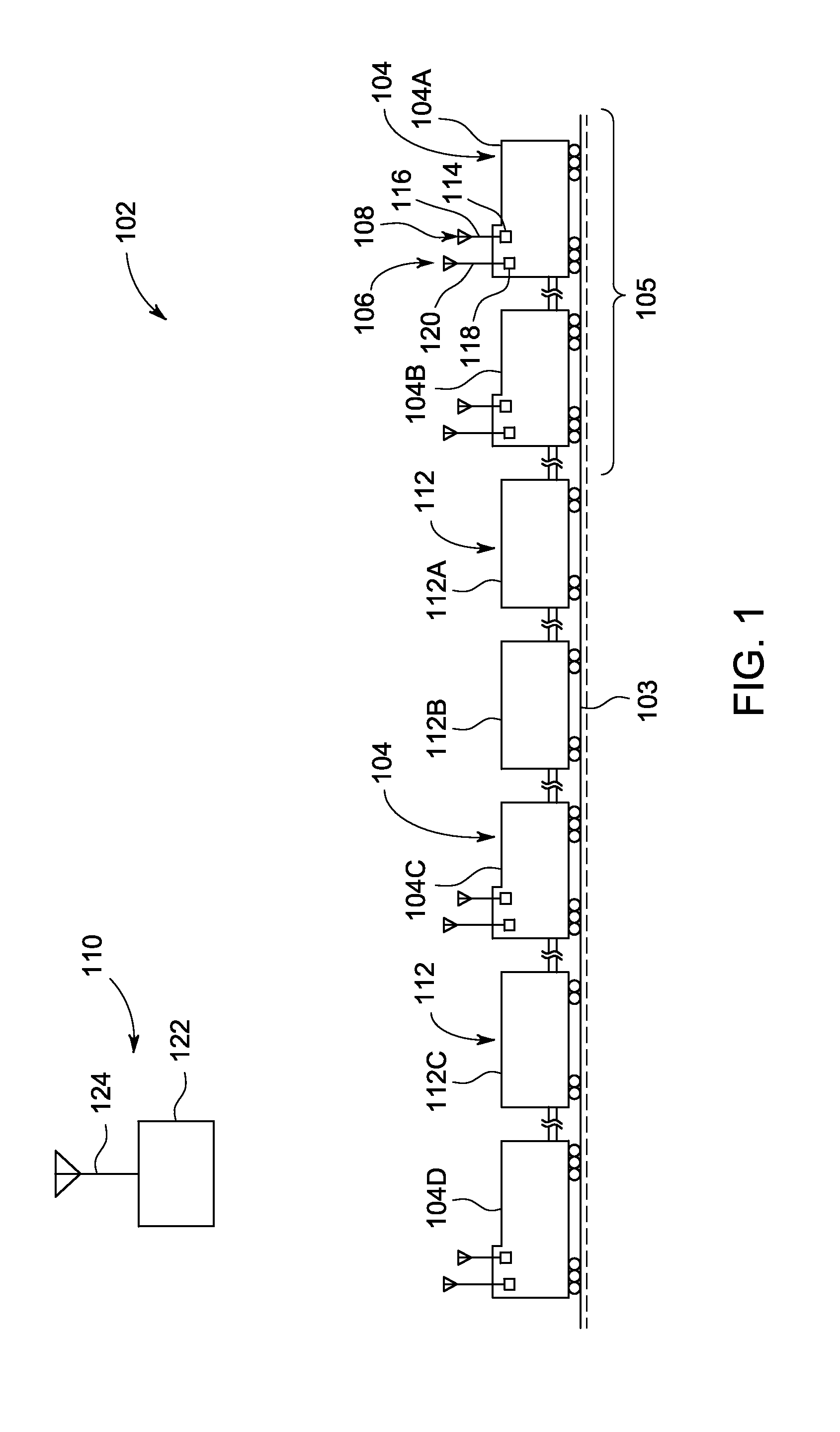
[0012]One or more embodiments disclosed herein describe a communication system and method used in conjunction with a vehicle system having plural propulsion-generating vehicles. Two or more of the propulsion-generating vehicles include wireless communication devices onboard the propulsion-generating vehicles. A first wireless communication device communicates remote data signals with a location disposed off-board the vehicle system. The remote data signals may be warning signals, such as signals communicated in a positive train control (PTC) system. As such, the first wireless communication device also is referred to as a remote wireless communication device. A second wireless communication device disposed onboard the propulsion-generating vehicles may be configured to communicate local data signals between the propulsion-generating vehicles, and is also referred to as a local wireless communication device. The local data signals may be signals used to control tractive efforts or br...


PUM


Abstract

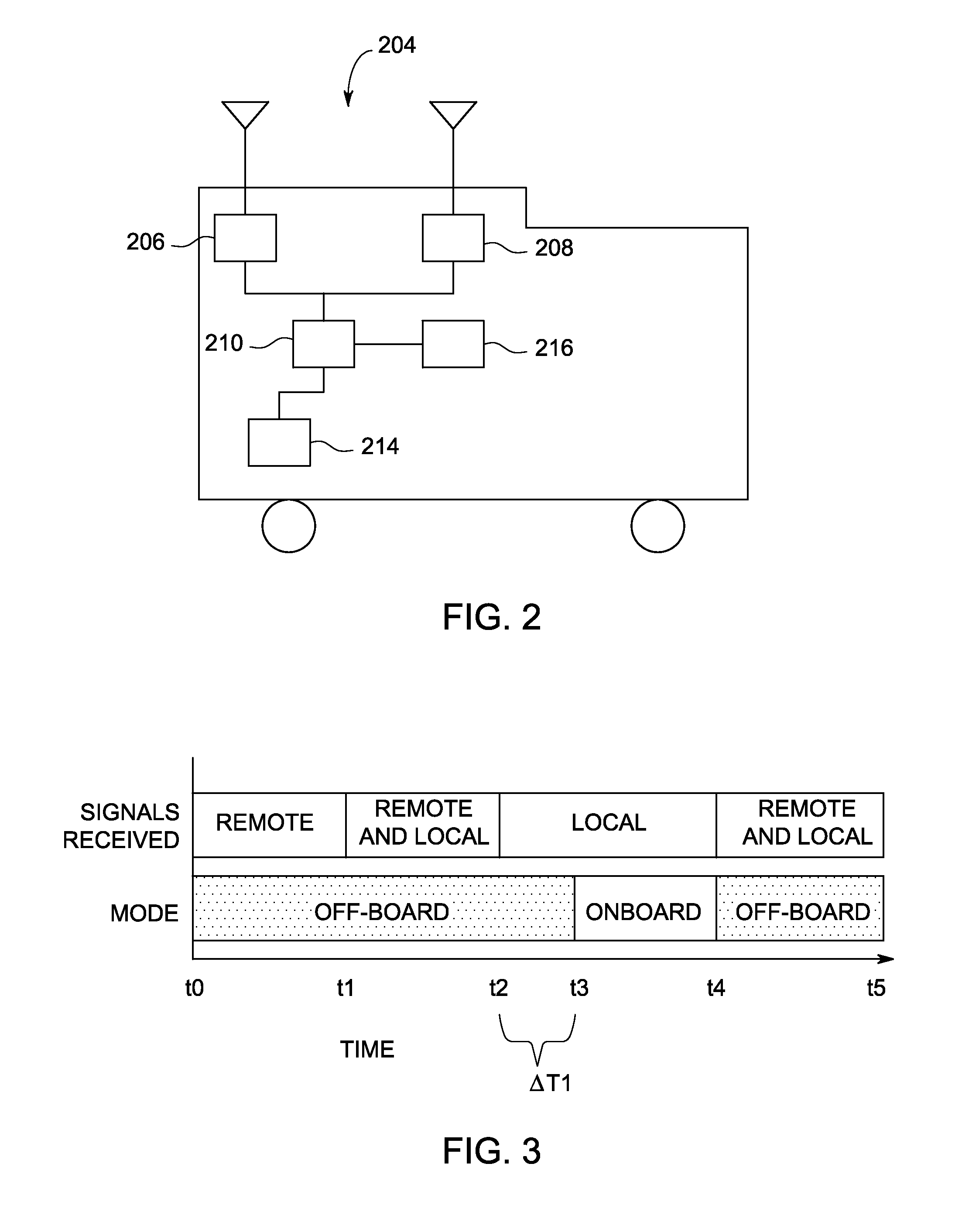
A communication system includes a first wireless communication device disposed onboard a vehicle system having two or more propulsion-generating vehicles that are mechanically interconnected with each other. The communication system also includes a controller configured to be disposed onboard the vehicle system and operatively connected with the first wireless communication device in order to control operations of the device. The controller is configured to direct the first wireless communication device to switch between operating in an off-board communication mode and an onboard communication mode. When the first wireless communication device is operating in the off-board communication mode, the device is configured to receive remote data signals from a location that is disposed off-board of the vehicle system. When the first wireless communication device is operating in the onboard communication mode, the device is configured to communicate local data signals between the propulsion-generating vehicles of the vehicle system.

Description

BACKGROUND[0001]Embodiments of the subject matter herein relate generally to signal communication systems and methods for a vehicle system.[0002]Some known vehicle systems include multiple vehicles connected together so that the vehicles can travel together. Such vehicle systems can be referred to as consists. For example, rail vehicle consists may include two or more locomotives (or other powered vehicles capable of self-propulsion) and one or more railcars (incapable of self-propulsion) connected together. The vehicles may communicate with each other locally to coordinate the movement of the vehicle system. The vehicles may also communicate with a remote location from the vehicle system.[0003]The local communications between vehicles in the vehicle system may include various signals containing messages relating to a wide range of information, including operation, safety, status, and confirmations, among a host of others. The potentially large number of local communications transmi...

Claims


Application Information

Patent Timeline
IPC IPC(8): B61C17/12G06F19/00
CPCG06F19/00B61C17/12
Inventor COOPER, JARED KLINEMANFOY, ROBERT JAMESPELTZ, DAVID MICHAELSMITH, EUGENE A.KELLNER, STEVEN ANDREWSCHROECK, BRIAN WILLIAMGILBERTSON, KEITH
Owner GENERAL ELECTRIC CO
Learn More