
Method for operating a wind power plant

a technology for wind power plants and wind power plants, applied in the direction of machines/engines, mechanical equipment, transportation and packaging, etc., can solve the problems of inconvenient use, power reduction of wind power plants, and the idea of using a nacelle anemometer of the reduced power plant, so as to achieve the effect of reducing energy outpu

Active Publication Date: 2014-07-03
SIEMENS GAMESA RENEWABLE ENERGY SERVICE GMBH
View PDF11 Cites 9 Cited by
  • Summary
  • Abstract
  • Description
  • Claims
  • Application Information

AI Technical Summary

Benefits of technology

The technical effect of this patent is to provide a method for operating a wind power plant with a reduced energy output set point to accurately determine the loss of output. This method is particularly useful when multiple wind power plants are involved, as it allows for a precise adjustment of the wind farm's power output and ensures uniform ageing of the wind power plants.

Problems solved by technology

With the operation of wind power plants it can occur that the wind power plants must be reduced in the power thereof due to external demands, for example from the network supplier, or due to disturbances.
Typically, however, there is no wind measurement mast in the proximity of a wind power plant, or respectively a wind farm, or respectively a wind measurement mast would indicate only approximate information about the actual wind speed at a wind power plant when for example, the wind power plant does not have freely inflowing wind or the wind measurement mast would not have appropriate freely inflowing wind, or respectively turbulent wind is present.
In addition, the idea to use a nacelle anemometer of the reduced power plant, or respectively the wind power plant, which is operated with a predefinable reduced energy output set point, is not suitable because the anemometer measurement is heavily distorted due to the rotor.
For the performance-optimized normal mode of the wind power plant, static anemometer corrections are used for this purpose which, however, are not applicable to the anemometer measurement values when the wind power plant is operated at a predefined reduced energy output set point, thus outside of the performance-optimized normal mode.

Method used


Image

  • Method for operating a wind power plant
  • Method for operating a wind power plant
  • Method for operating a wind power plant

Examples


Embodiment Construction

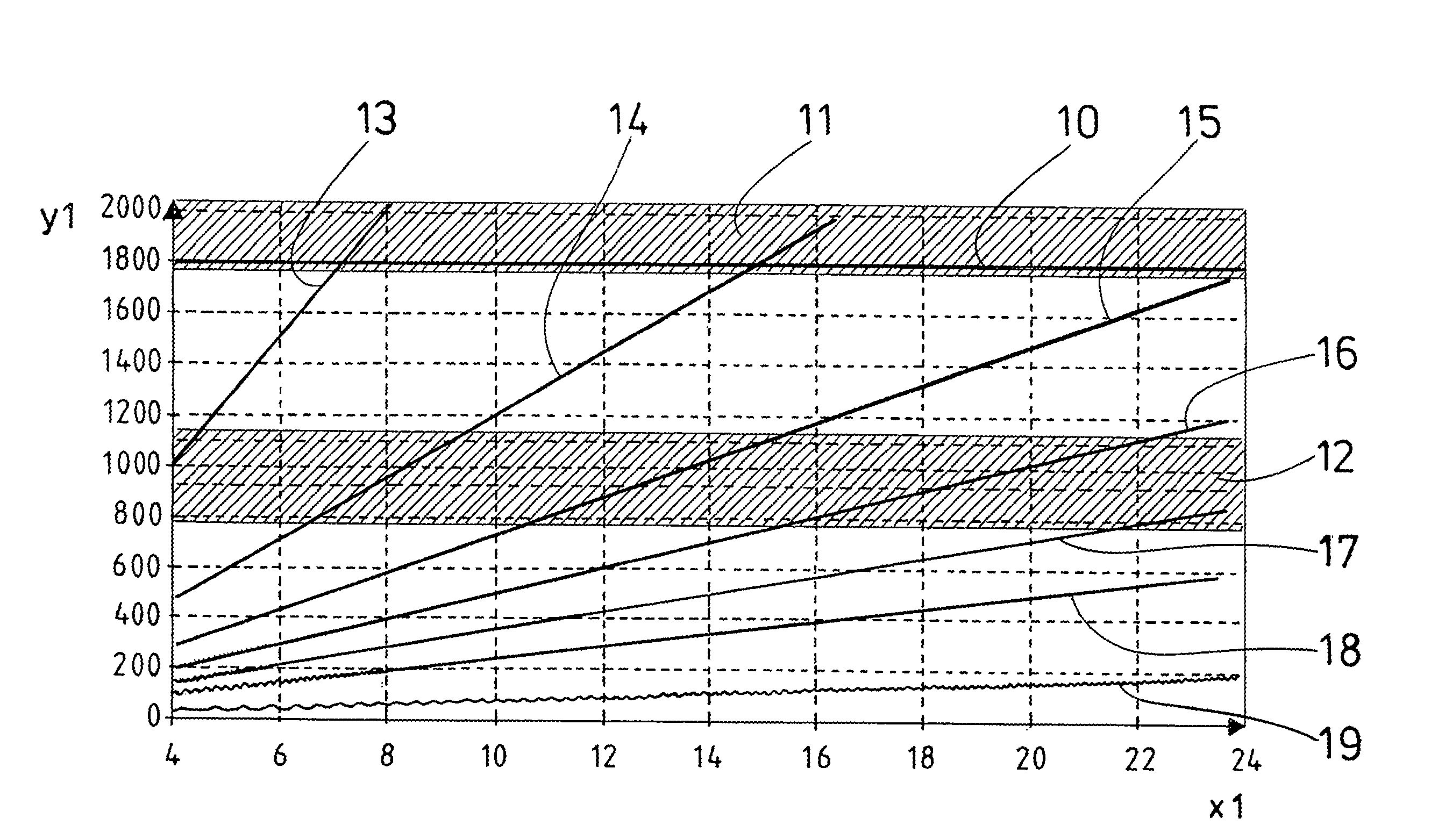
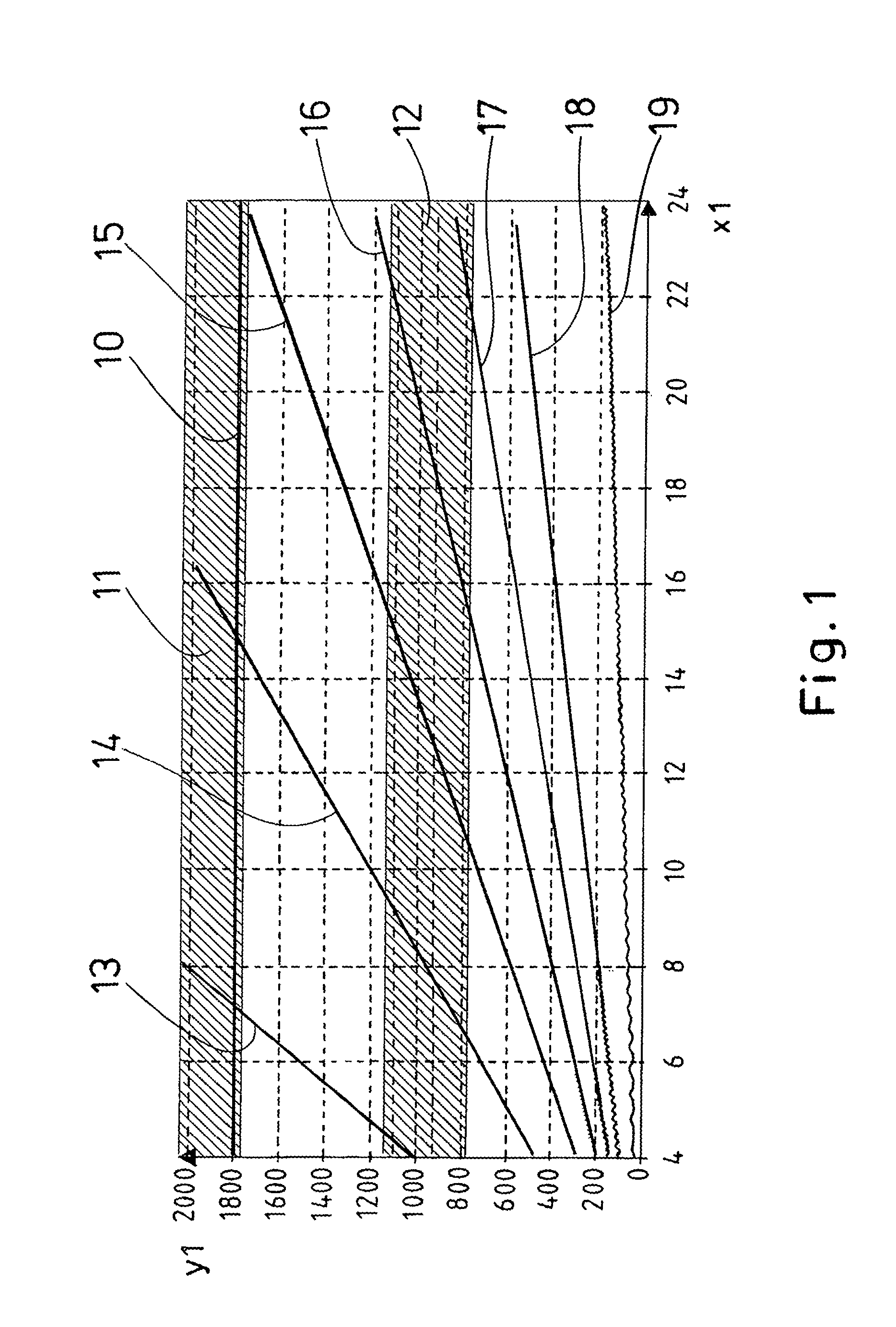
[0042]FIG. 1 shows a schematic diagram of idling rotational speeds of a wind power plant which is operated with a reduced energy output set point of 0% of the nominal power, or respectively the nominal energy output, of the wind power plant. The generator rotational speed Y1 is plotted in RPM, and the wind speed X1 in m / s. In addition, FIG. 1 shows at 1800 RPM the nominal rotational speed 10 and a prohibited rotational speed range 11 and a prohibited rotational speed range 12. The prohibited rotational speed range 11 is prohibited with a wind power plant operated without power because otherwise dangerous high rotational speeds with high centrifugal forces would arise too quickly. The prohibited rotational speed range 12 lies at the resonance frequencies of the wind power plant. In operation, the rotational speed should be driven quickly through the prohibited rotational speed range 12.

[0043]FIG. 1 shows that with different blade angles, or respectively pitch angles, the idling rotat...


PUM


Abstract

A method for operating a wind power plant having at least one rotor blade, the blade angle of which can be adjusted. The wind power plant is operated with a predefinable reduced energy output set point. To determine the potential output, at least one predefinable operating parameter of the wind power plant is measured and is applied to at least one stored characteristic curve for the reduced energy output set point. The actual energy output is determined and the loss in the output is formed from the difference between the potential output and the actual energy output.

Description

BACKGROUND OF THE INVENTION[0001]1. Field of the Invention[0002]The invention relates to a method for operating a wind power plant having at least one rotor blade, the blade angle of which can be adjusted, wherein the wind power plant is operated with a predefinable reduced energy output set point.[0003]2. Description of Related Art[0004]With the operation of wind power plants it can occur that the wind power plants must be reduced in the power thereof due to external demands, for example from the network supplier, or due to disturbances. With a reduction of power of the wind power plant that is not caused by the operator of the wind power plant but rather by the network supplier for example, it is necessary to quantify the lost energy output because as a rule someone has to provide compensation payments for this output that was not realized.[0005]If there is a wind measurement mast in the proximity of the wind power plant or the wind farm, the potential output of the wind power pla...

Claims


Application Information

Patent Timeline
Patent Type & Authority Applications(United States)
IPC IPC(8): F03D7/02F03D7/04
CPCF03D7/04F03D7/0224G01W1/02F05B2270/32F03D7/028F03D7/043F05B2270/335Y02E10/72
Inventor BOHME, SEBASTIANGOLLNICK, BERT
Owner SIEMENS GAMESA RENEWABLE ENERGY SERVICE GMBH
Learn More