
System and method for controlling an arc welding process

a technology of arc welding and control parameters, applied in the field of control of parameters of arc welding process, can solve problems such as difficulty in accurately determining voltage drop across the welding ar

Active Publication Date: 2014-07-03
ILLINOIS TOOL WORKS INC
View PDF3 Cites 53 Cited by
  • Summary
  • Abstract
  • Description
  • Claims
  • Application Information

AI Technical Summary

Benefits of technology

This patent describes a welding system that uses sensors to detect the intensity of light and electricity in the welding arc, and then modifies the light intensity based on the detected current to control various welding parameters. This results in a more stable and efficient welding process. In simpler terms, this patent describes a system that ensures the right amount of electricity and light are supplied to the welding arc for optimal results.

Problems solved by technology

Unfortunately, it is difficult to accurately determine the voltage drop across the welding arc due to changes in the extension of the electrode as it is advanced toward the workpiece, as well as other voltage drops that are difficult to account for.

Method used


Image

  • System and method for controlling an arc welding process
  • System and method for controlling an arc welding process
  • System and method for controlling an arc welding process

Examples


Embodiment Construction

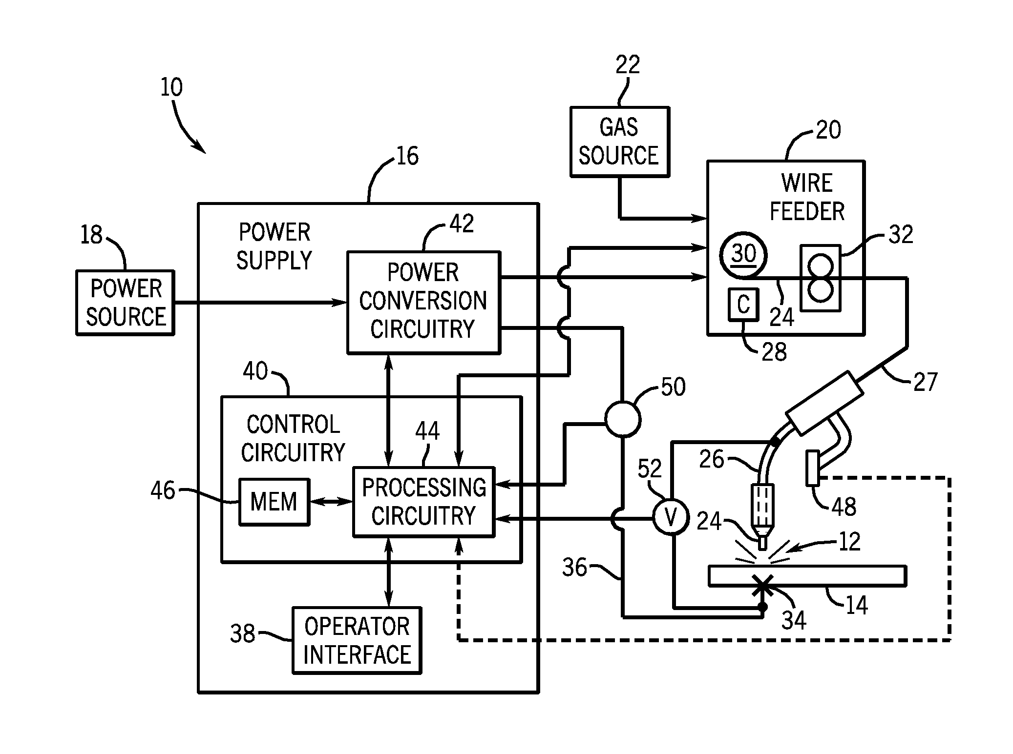
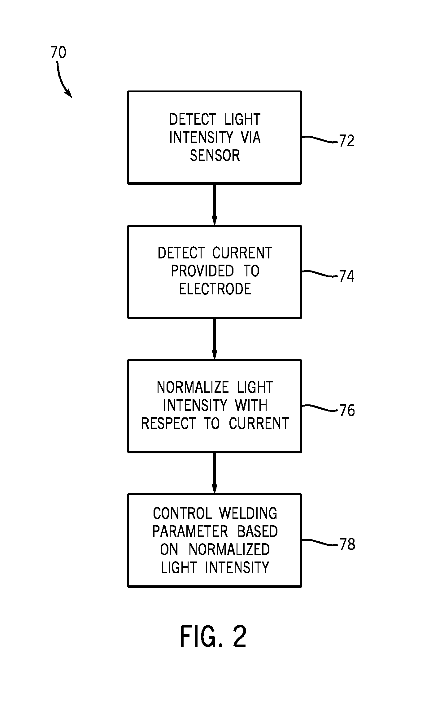
[0018]Embodiments of the present disclosure are directed toward systems and methods for controlling welding system parameters based on a sensed light intensity of the welding arc produced by the welding system. In addition to a light sensor used to detect the light intensity, the welding system includes a current sensor to determine the current flowing through the welding electrode to produce the arc. Control circuitry may receive signals corresponding to the detected light intensity and the detected current, and process the signals to determine a modified light intensity that is directly proportional to the length of the welding arc. This may involve modifying the detected light intensity with respect to the detected current. Since the modified light intensity corresponds with welding arc length, the welding system may utilize the modified light intensity as a primary feedback parameter to control the arc length. More specifically, the control circuitry may send control signals to ...


PUM

PropertyMeasurementUnit
Lengthaaaaaaaaaa
Speedaaaaaaaaaa
Electric potential / voltageaaaaaaaaaa

Abstract

A welding system includes an electrode configured to be advanced toward a workpiece and a power supply configured to provide a flow of electricity to the electrode for generating a welding arc between the electrode and the workpiece. The welding system also includes a first sensor configured to sense a light intensity of the welding arc and a second sensor configured to sense a current provided to the electrode via the power supply. In addition, the welding system includes a controller communicatively coupled with the first and second sensors and configured to modify the light intensity with respect to the current. The controller is configured to control a welding parameter of the welding system based on the modified light intensity.

Description

BACKGROUND[0001]The invention relates generally to welding systems and, more particularly, to controlling parameters of an arc welding process.[0002]A wide range of welding systems and welding control regimes have been implemented for various purposes. In continuous welding operations, gas metal arc welding (GMAW) techniques allow for formation of a continuous weld bead by feeding filler material shielded by inert or active gas from a welding torch. Electrical power is applied to the welding wire and a circuit is completed through the workpiece to sustain an arc that melts the wire and the workpiece to form the desired weld. Certain related processes do not use shielding gas, and may rely upon constituents in the welding wire for forming and protecting the progressing weld.[0003]In its various forms, GMAW welding involves application of controlled voltages and currents to a welding wire that forms an electrode and is advanced towards a workpiece to create an arc between the electrod...

Claims


Application Information

Patent Timeline
IPC IPC(8): B23K9/10
CPCB23K9/10B23K9/0956B23K9/322
Inventor HUTCHISON, RICHARD MARTINSCOTT, KEVIN MICHAEL
Owner ILLINOIS TOOL WORKS INC
Learn More