
Caisson Breakwater Module

Inactive Publication Date: 2014-07-03
ELECTRIC WAVES
View PDF8 Cites 19 Cited by
  • Summary
  • Abstract
  • Description
  • Claims
  • Application Information

AI Technical Summary

Benefits of technology

The patent describes a modular built-up of a caisson breakwater that includes an OWC. The base and lid of the breakwater are separate manufactures and can be easily installed. The design makes it easier and less expensive to install and maintain the OWC compared to a floating structure. The breakwater also provides a sealed chamber for electrical cables and converters, which can protect them from sea water and other environmental influences. This design reduces the life-cycle-cost of the breakwater and allows for the use of the generated electricity locally. The breakwater can also be protected from high waves or storms. The lid is made of prefabricated sections, making it easier to install. Additionally, the breakwater can include wind turbines, photovoltaic panels, and even desalination plants to generate more electricity and provide freshwater locally.

Problems solved by technology

Even though these particular prior art systems offer an advantageous combination of coastal protection and electricity generation from renewable energy, the prior art designs suffer from various drawbacks.
In general, their designs do not take cost-efficiency and economic viability into account.

Method used


Image

  • Caisson Breakwater Module
  • Caisson Breakwater Module
  • Caisson Breakwater Module

Examples


first embodiment

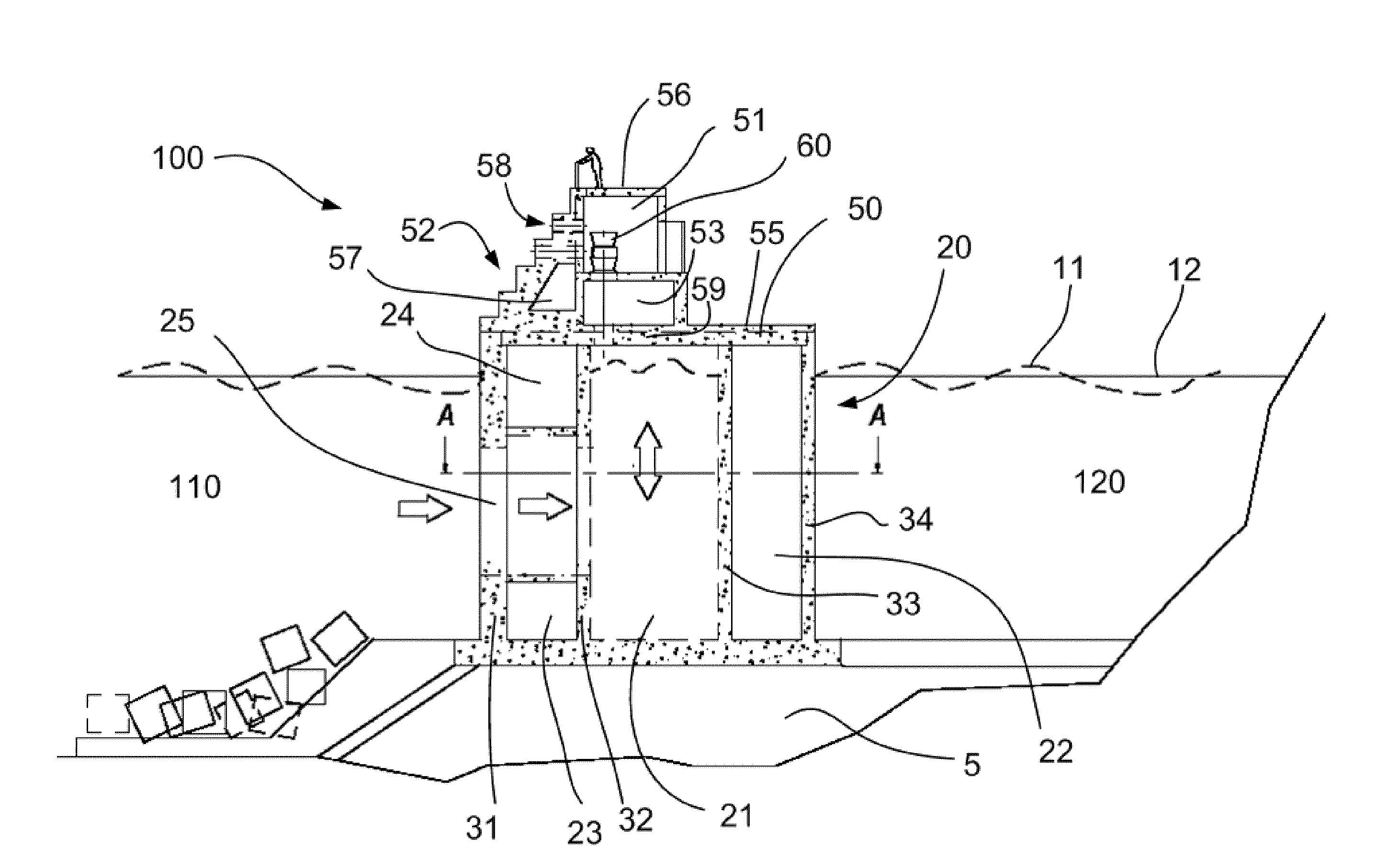
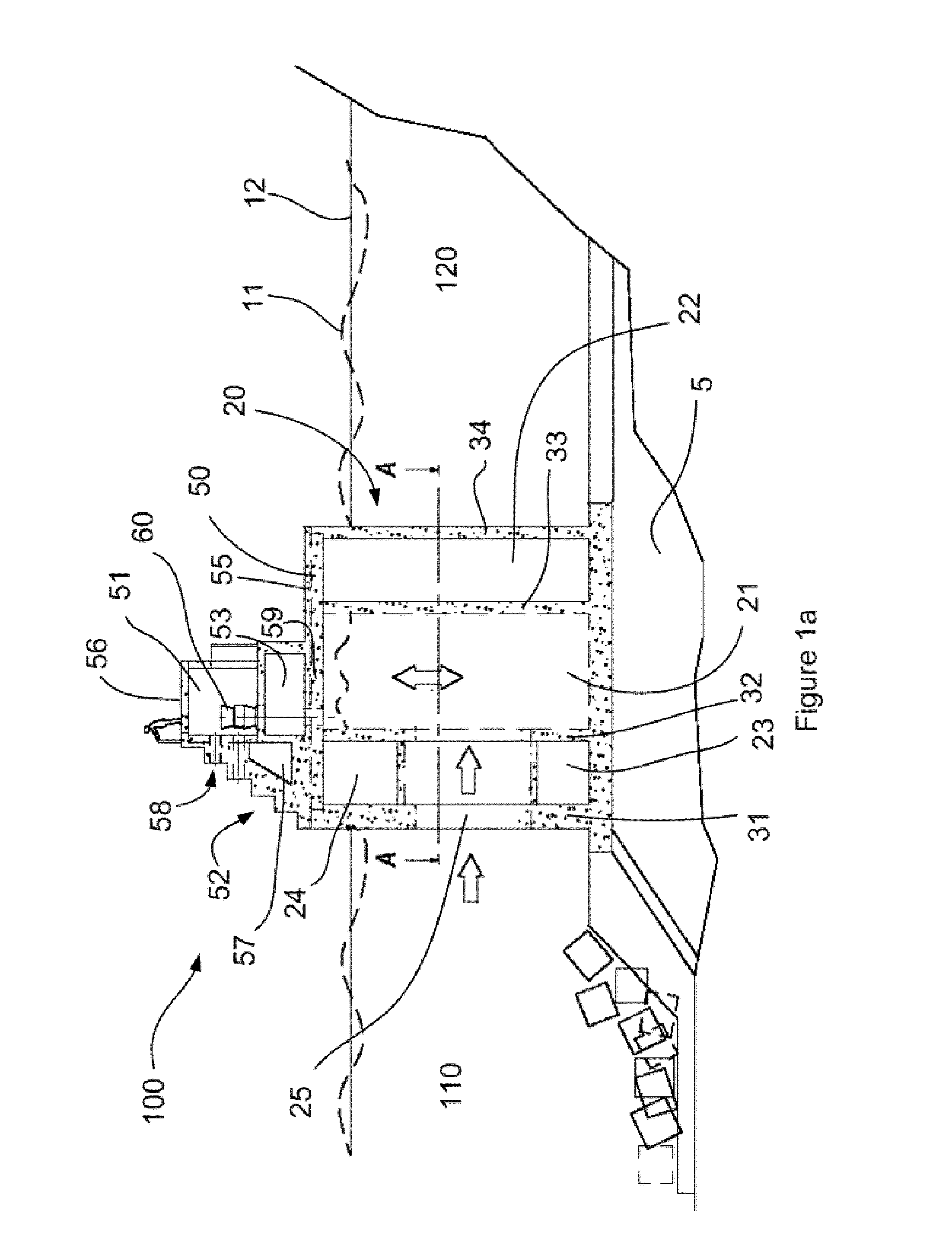
[0027]FIG. 1a illustrates a cross-sectional view of a caisson breakwater module 100. The breakwater module has an upwave side 110, from which the waves strike upon the module and a downwave side 120, where the sea will generally be calmer. On the downwave side 120, e.g. a port or harbour may be located. The breakwater module may thus form a protective barrier for the port and any boats present in the port.

[0028]Reference sign 12 indicates the water level, whereas reference sign 11 indicates the height of the waves. The module comprises a base 20 installed on sea bed 5. A lid 50 may be placed on top of the base to form the breakwater module 100.

[0029]An Oscillating Water Column (OWC) is provided in the breakwater module. The OWC may comprise a substantially horizontal water inlet 25. Water enters through the inlet, and due to the sea's wave action, a water column will oscillate in water oscillation chamber 21. The oscillating water column causes an oscillating air flow through air ch...

fourth embodiment

[0046]FIGS. 4a-4d illustrate various views of a module according to a Similar components have once again been indicated with the same reference signs. From FIG. 4a, the sealed chamber 57, turbine chamber 51, water inlet 25, and wind turbine 70 are readily recognizable. Contrary to previously shown embodiments, the rear lid section behind the turbine chamber is not a substantially flat surface on top of base 20. Instead, in this embodiment, a covered space 97 underneath the deck is provided. This space may be substantially closed or open towards the sea. The covered space 97 may be divided into separate chambers 97a and 97b. These chambers may potentially serve many different purposes.

[0047]In the particular embodiment shown, the chambers are used for housing a desalination and water storage system. Desalination machinery 99 may be housed in chamber 97a. Fresh water resulting from the desalination process may be stored in chamber 97b. This fresh water may be used locally, e.g. in a ...


PUM


Abstract

A caisson breakwater module having an upwave and a downwave side and incorporating an oscillating water column, the caisson breakwater comprising a base installed on the sea bed and a lid adapted to be positioned on top of said base, the base defining a water inlet on the upwave side and further defining a water oscillation chamber, and the lid defining a breakwater section on the upwave side, a turbine chamber, one or more air ducts connected with said turbine chamber and an additional substantially sealed chamber. The invention further relates to a breakwater comprising a plurality of such modules and a lid suitable for use in such modules.

Description

[0001]The present invention relates to a caisson breakwater, and more particularly relates to a caisson breakwater module incorporating an Oscillating Water Column (OWC). The present invention further relates to a breakwater structure comprising a plurality of such modules and to a lid particularly suitable for such a module.BACKGROUND ART[0002]Breakwater structures are structures that generally serve to reduce the erosion of a coast by reducing the intensity of wave actions. They may be built at or near the coast and may be used as a protective border of a harbour or port. It is also known to use them offshore (i.e. further away from the coast), with the same scope of protecting the coast e.g. a beach.[0003]Breakwater structures may be built with one end linked to the coast or completely separated from the coast. It is known to provide floating breakwater structures or to construct them on a foundation on the sea bed. Breakwaters of different types are known: on the one hand, rubbl...

Claims


Application Information

Patent Timeline
IPC IPC(8): E02B3/06
CPCE02B3/06E02B9/08F03B13/142F05B2210/404F05B2220/62F05B2220/708F05B2240/40Y02A10/11Y02E10/30F03B13/24
Inventor CANALS, XAVIER TOUS IAUGUET, GUILLEM PASTOR I
Owner ELECTRIC WAVES
Learn More