
Integrated electronic device for monitoring mechanical stress within a solid structure

a solid structure and electronic device technology, applied in the direction of force measurement using piezo-resistive materials, acceleration measurement using interia forces, instruments, etc., can solve the problems of damage to the system, unsatisfactory reliability of a sip such as the one described in u.s. patent no. 6,950,767,

Active Publication Date: 2014-07-03
STMICROELECTRONICS INT NV
View PDF9 Cites 17 Cited by
  • Summary
  • Abstract
  • Description
  • Claims
  • Application Information

AI Technical Summary

Benefits of technology

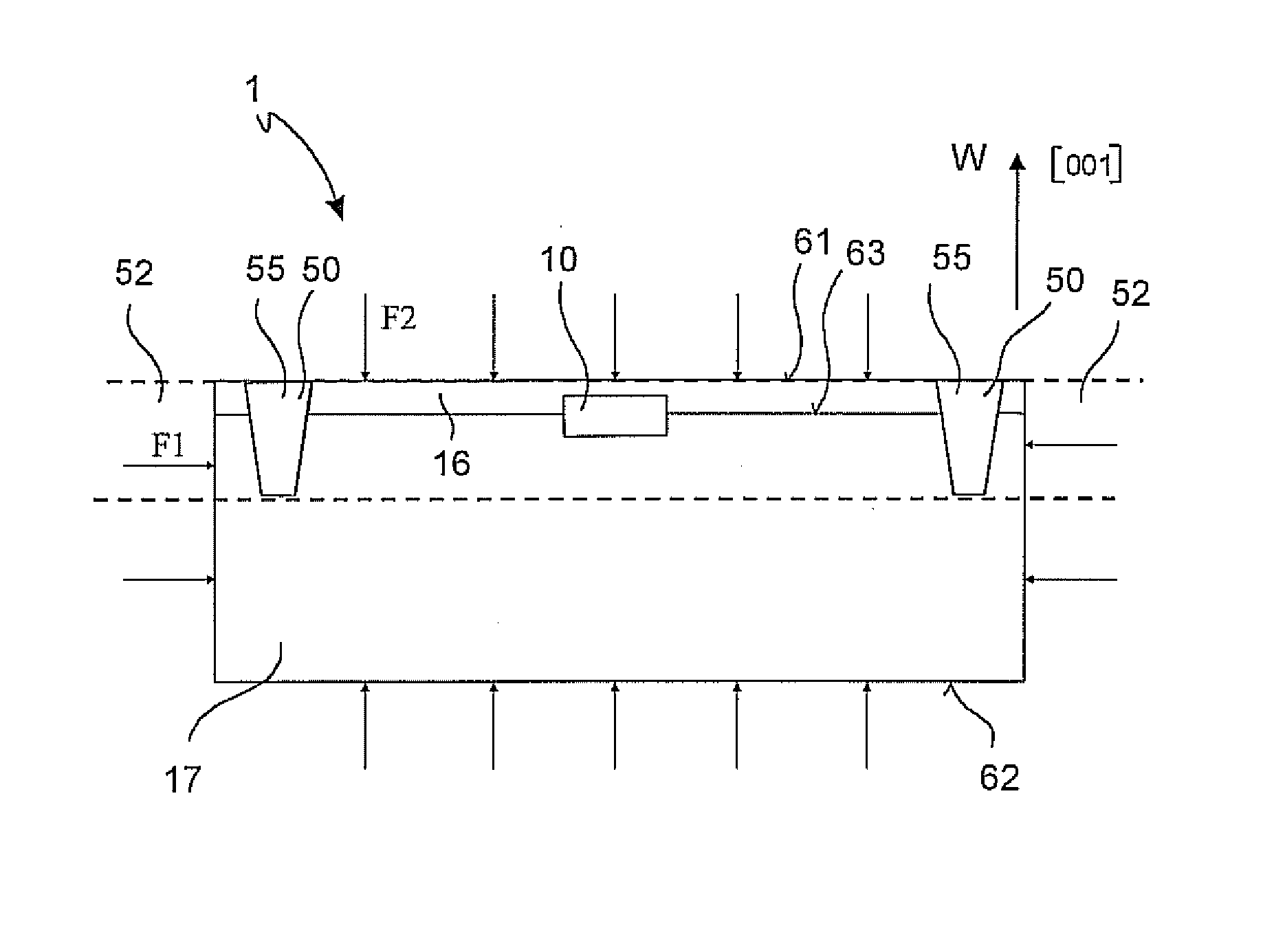
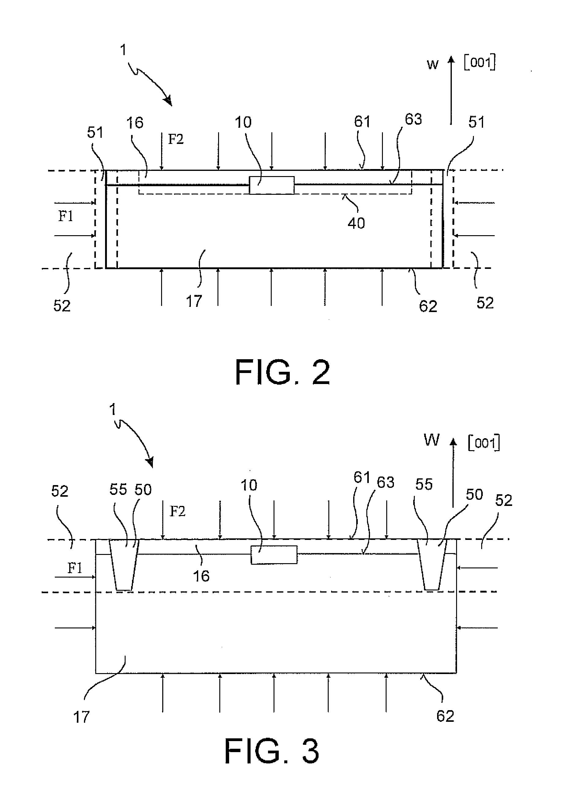
The present invention provides an improved integrated electronic device for detecting force, pressure, and mechanical stress within a solid structure. The device includes a sensor that detects the local parameter associated with a force observed in a given direction. A damping element is integrated in the device to damp forces acting in a planar region perpendicular to the given direction. The technical effects of the invention include improved accuracy and reliability in detecting local parameters and reducing interference from external forces.

Problems solved by technology

However, it should be understood that a SiP, which is intended to be first “drowned” in a construction material (e.g. liquid concrete, which will then solidify) and then remain “buried” within the solid structure, is subjected to adverse conditions, for example due to very high pressures, which can even be as high as several hundreds of atmospheres.
In addition, a number of other causes of wear exist, over time, for example, due to water seepages, which can damage the system.
In view of the above, the level of reliability of a SiP such as the one described in U.S. Pat. No. 6,950,767 may not be fully satisfactory.
However, the following drawbacks will usually arise: i) as stated above, the result of the sensor measurement does not correspond to the vertical component; ii) the result of the sensor measurement may not correspond even to the actual intensity of the force, as the two vertical and transversal components may result as being weighted differently by different sensitivity values; iii) is not possible to differentiate the two components, nor measure them separately; and iv) in case the lateral force is desired to be measured, this cannot be done by simply orientating the sensor so as to align the direction of maximum sensitivity with one of the axes or [100].
In fact, in this case, the result would be influenced also by the component along the axis [001], which in this example is aligned with the vertical direction, and thus is affected by the weight of the structure, which may totally impair the correctness and accuracy of the result.
This desire, due to the above reasons, may not met by the prior art devices mentioned above.

Method used


Image

  • Integrated electronic device for monitoring mechanical stress within a solid structure
  • Integrated electronic device for monitoring mechanical stress within a solid structure
  • Integrated electronic device for monitoring mechanical stress within a solid structure

Examples


Embodiment Construction

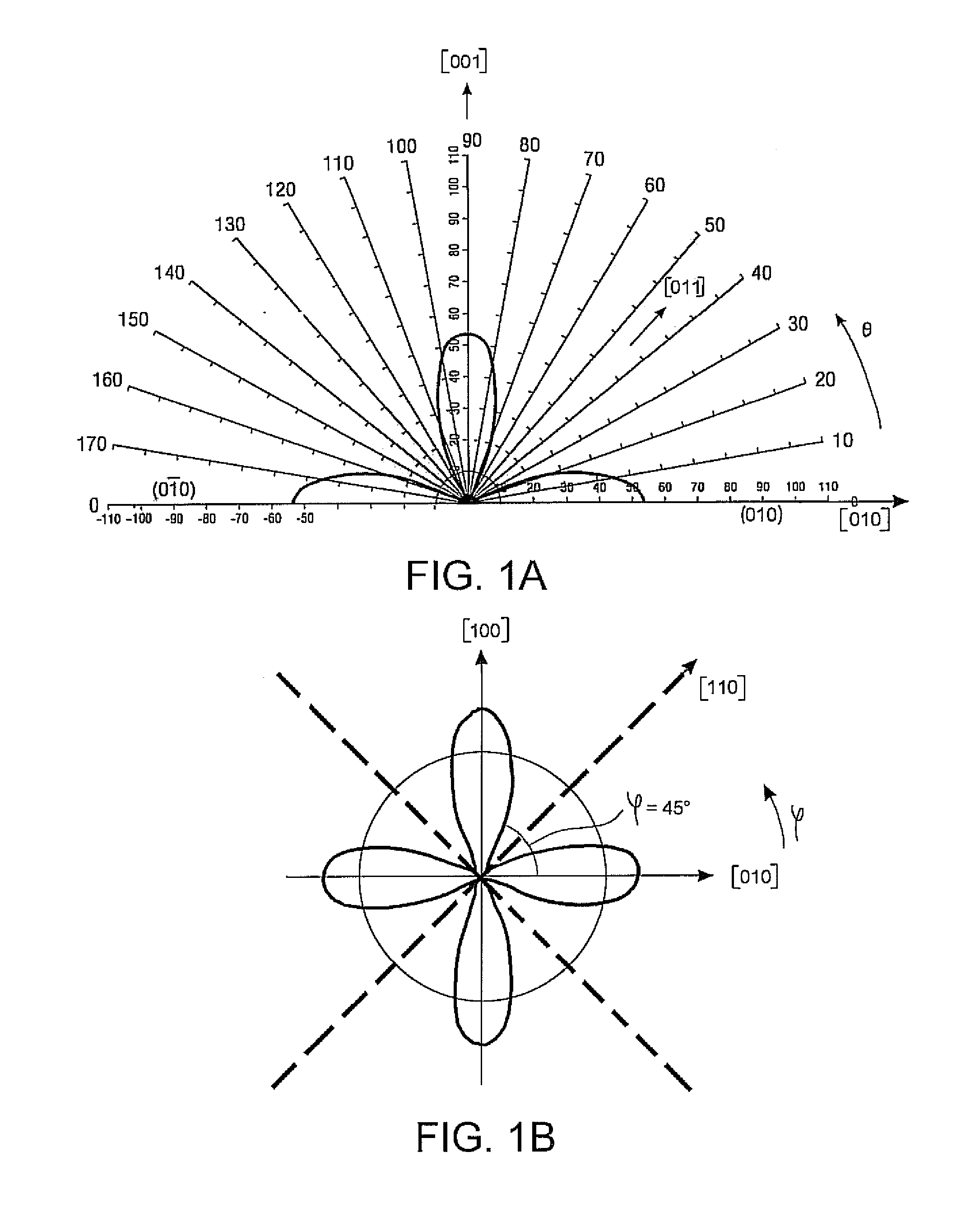
[0034]Prior to the description of the device according to the invention, it is useful to recall some principles relevant to the piezo-resistive effect (on which the force / pressure sensors comprised in the device are based, as will be illustrated below), and to establish some conventions related to the space reference systems being considered herein. A pressure sensor of the type described herein is capable of converting a pressure value to an electric variable, for example by exploiting the known variations that the mechanical stress caused by the pressure on the semiconductor (e.g., silicon) induces for example to the mobility of electrons / holes in the same semiconductor.

[0035]It is known, to this purpose, that the mobility depends on the pressure in a manner dependent on the crystalline orientation of the semiconductor material, according to the laws that regulate the piezo-resistivity phenomenon. Particularly, with reference to Miller indices, using common notations in the contex...


PUM

PropertyMeasurementUnit
Young's modulusaaaaaaaaaa
mechanical stressaaaaaaaaaa
forceaaaaaaaaaa

Abstract

The integrated electronic device is for detecting a local parameter related to a force observed in a given direction, within a solid structure. The device includes at least one sensor configured to detect the above-mentioned local parameter at least in the given direction through piezo-resistive effect. At least one damping element, integrated in the device, is arranged within a frame-shaped region that is disposed around the at least one sensor and belongs to a substantially planar region comprising a plane passing through the sensor and perpendicular to the given direction. Such at least one damping element is configured to damp forces acting in the planar region and substantially perpendicular to the given direction.

Description

FIELD OF INVENTION[0001]The present invention relates to integrated electronic devices for detecting a locally observed force and / or pressure and / or mechanical stress, within a solid structure, in a specific direction. A system for monitoring a force and / or pressure and / or mechanical stress, within a solid structure, using the above-mentioned device is also included.BACKGROUND OF THE INVENTION[0002]In solid structures, in particular in load-bearing structures of, for example, bridges, buildings, tunnels, railways, containment walls, dams, embankments, slabs and beams of buildings, underground piping and structures of urban subways, and the like, it is very important to monitor, in several points, significant parameters, particularly mechanical stresses (and thus those forces and / or pressures causing the stresses) to which the structure is subjected in those points. In the present description, solid structures are considered such as structures made from building material, for example...

Claims


Application Information

Patent Timeline
Patent Type & Authority Applications(United States)
IPC IPC(8): G01L1/18H01L27/20H10N39/00
CPCH01L27/20G01L1/18H10N39/00
Inventor PAGANI, ALBERTOZIGLIOLI, FEDERICO GIOVANNIMURARI, BRUNO
Owner STMICROELECTRONICS INT NV
Learn More