Optimizing lithographic processes using laser annealing techniques

Active Publication Date: 2014-06-26
GLOBALFOUNDRIES US INC
View PDF1 Cites 5 Cited by
  • Summary
  • Abstract
  • Description
  • Claims
  • Application Information

AI Technical Summary

Benefits of technology

The present invention relates to methods for improving the results of lithographic processes, such as directed self assembly (DSA), using laser annealing. The methods involve subjecting a substrate to a lithographic process and then applying a set of laser annealing passes to optimize the process. The techniques used for the laser annealing passes can include varying the beam characteristics and applying additional processing techniques. The invention provides methods for optimizing each stage of the lithographic process, resulting in improved accuracy and efficiency.

Problems solved by technology

Incomplete processing may cause defects in the desired pattern.
If this cooling is not properly controlled, defects may be present in the final pattern.
That is, long bake times reduce throughput and increase cost, while high temperature baking risks oxidizing or otherwise damaging the BCP material and preventing self-assembly and full alignment.

Method used


Image

  • Optimizing lithographic processes using laser annealing techniques
  • Optimizing lithographic processes using laser annealing techniques
  • Optimizing lithographic processes using laser annealing techniques

Examples


Embodiment Construction

[0026]Illustrative embodiments will now be described more fully herein with reference to the accompanying drawings, in which embodiments are shown. This disclosure may, however, be embodied in many different forms and should not be construed as limited to the embodiments set forth herein. Rather, these embodiments are provided so that this disclosure will be thorough and complete and will fully convey the scope of this disclosure to those skilled in the art. In the description, details of well-known features and techniques may be omitted to avoid unnecessarily obscuring the presented embodiments.

[0027]The terminology used herein is for the purpose of describing particular embodiments only and is not intended to be limiting of this disclosure. As used herein, the singular forms “a”, “an”, and “the” are intended to include the plural forms as well, unless the context clearly indicates otherwise. Furthermore, the use of the terms “a”, “an”, etc., do not denote a limitation of quantity,...


PUM


Abstract

Approaches for utilizing laser annealing to optimize lithographic processes such as directed self assembly (DSA) are provided. Under a typical approach, a substrate (e.g., a wafer) will be subjected to a lithographic process (e.g., having a set of stages / phases, aspects, etc.) such as DSA. Before or during such process, a set of laser annealing passes / scans will be made over the substrate to optimize one or more of the stages. In addition, the substrate could be subjected to additional processes such as hotplate annealing, etc. Still yet, in making a series of laser annealing passes, the techniques utilized and / or beam characteristics of each pass could be varied to further optimize the results.

Description

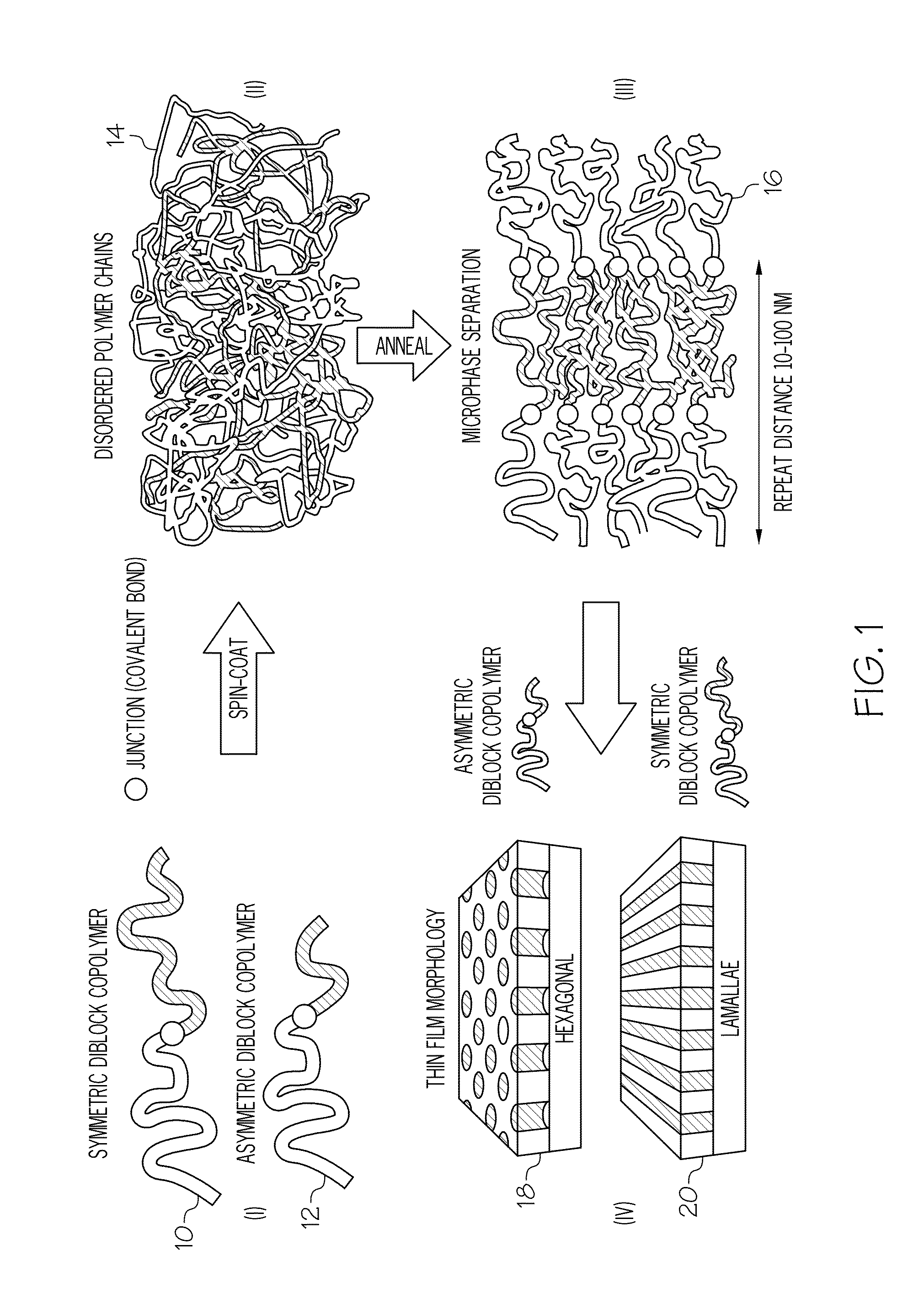
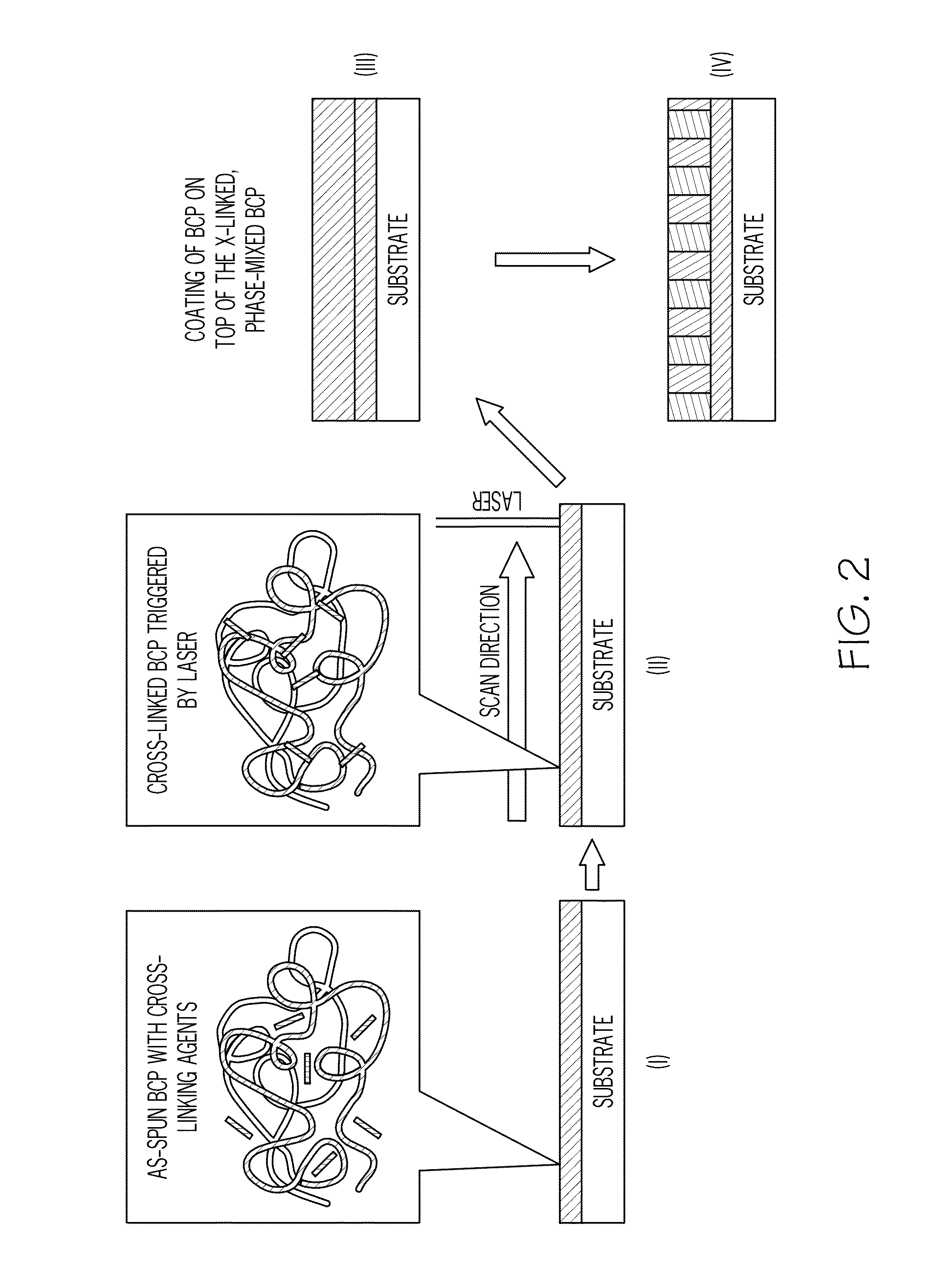
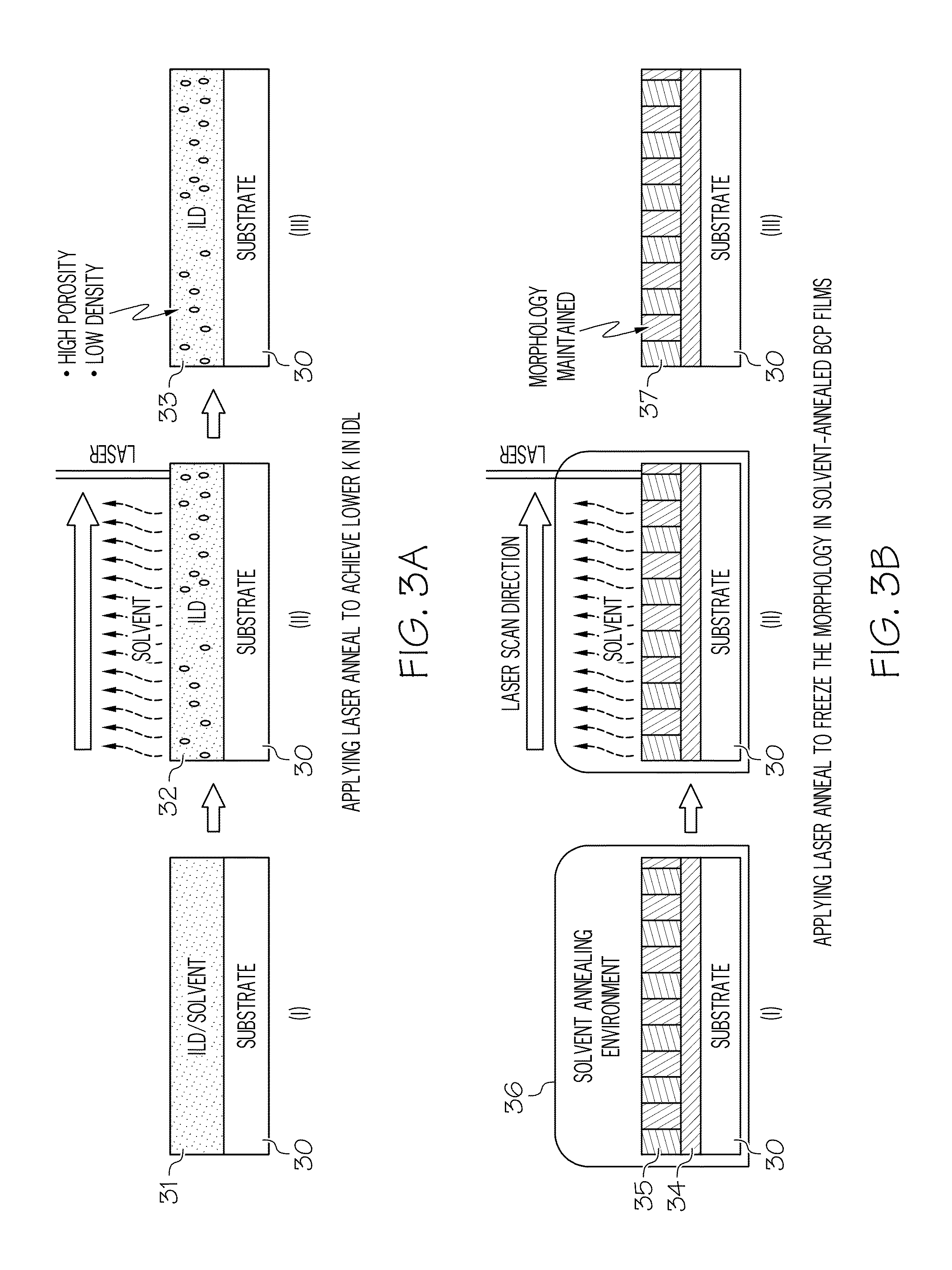
BACKGROUND[0001]1. Technical Field[0002]This invention relates generally to the field of semiconductors and, more particularly, to utilizing laser annealing techniques for optimizing lithographic processes such as directed self assembly.[0003]2. Related Art[0004]Directed self assembly (DSA) typically requires an annealing processing step, which causes block co-polymers (BCPs) to micro-phase separate and aligns the micro-domains in a thermodynamically preferred orientation. Incomplete processing may cause defects in the desired pattern. Moreover, after processing, the wafers must be cooled back down to room temperature. If this cooling is not properly controlled, defects may be present in the final pattern. One existing approach resolving this is to subject the wafer to very long bakes, or to bake at elevated temperatures, neither of which is desirable. That is, long bake times reduce throughput and increase cost, while high temperature baking risks oxidizing or otherwise damaging th...

Claims


Application Information

Patent Timeline
IPC IPC(8): G03F7/20
CPCG03F7/0002
Inventor E PREIL, MOSHESCHMID, GERARD M.FARRELL, RICHARD A.XU, JIWALLOW, THOMAS I.
Owner GLOBALFOUNDRIES US INC
Why Eureka
Try Eureka