
Time-interleaved digital-to-time converter

a digital-to-time converter and interleaved technology, applied in the direction of pulse counters, pulse manipulation, pulse techniques, etc., can solve the problems of requiring precise duty cycles of reference clocks or long absolute delays of prior art approaches

Active Publication Date: 2014-06-26
SILICON LAB INC
View PDF13 Cites 34 Cited by
  • Summary
  • Abstract
  • Description
  • Claims
  • Application Information

AI Technical Summary

Benefits of technology

The patent text describes a circuit and method for adjusting a clock signal using a fractional-N divider circuit and a digital to time converter circuit. The circuit includes a first capacitor and a second capacitor, which are selectively coupled to a current source. The method involves charging the first capacitor with a first current based on a first quantization error and the second capacitor with a second current, a fixed value, to generate a first pulse of the output clock. The second capacitor is then charged with a third current based on a second quantization error and the fixed value to generate a second pulse of the output clock. The adjusted divided clock signal includes two pulses with delayed edges, which have linearly proportional delays to the quantization errors. The technical effect of this patent text is to provide an improved adjustment of the clock signal with reduced delay and improved accuracy.

Problems solved by technology

However, various prior art approaches may have a long absolute delay through the interpolator or require precise duty cycles of the reference clock.

Method used


Image

  • Time-interleaved digital-to-time converter
  • Time-interleaved digital-to-time converter
  • Time-interleaved digital-to-time converter

Examples


Embodiment Construction

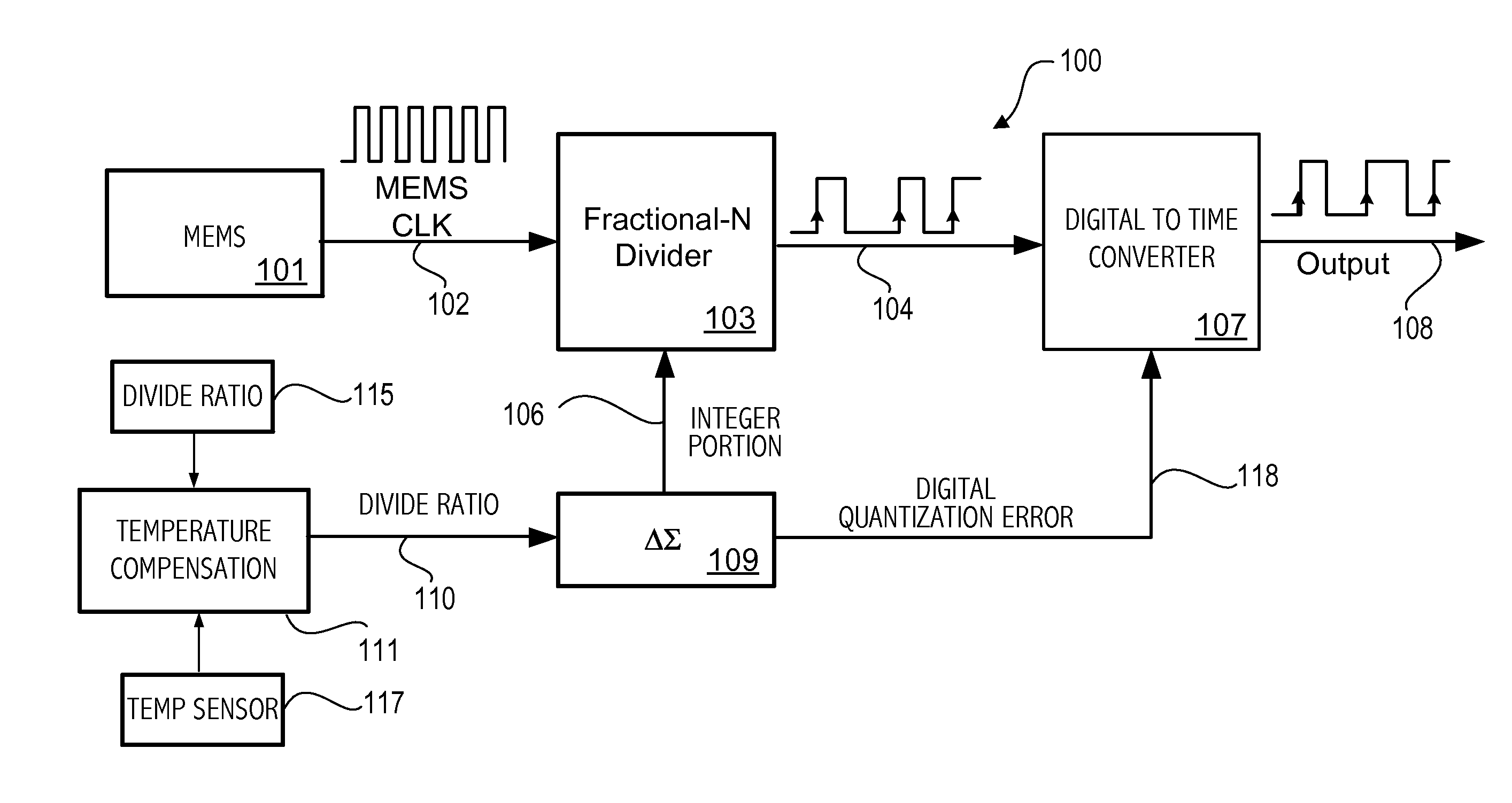
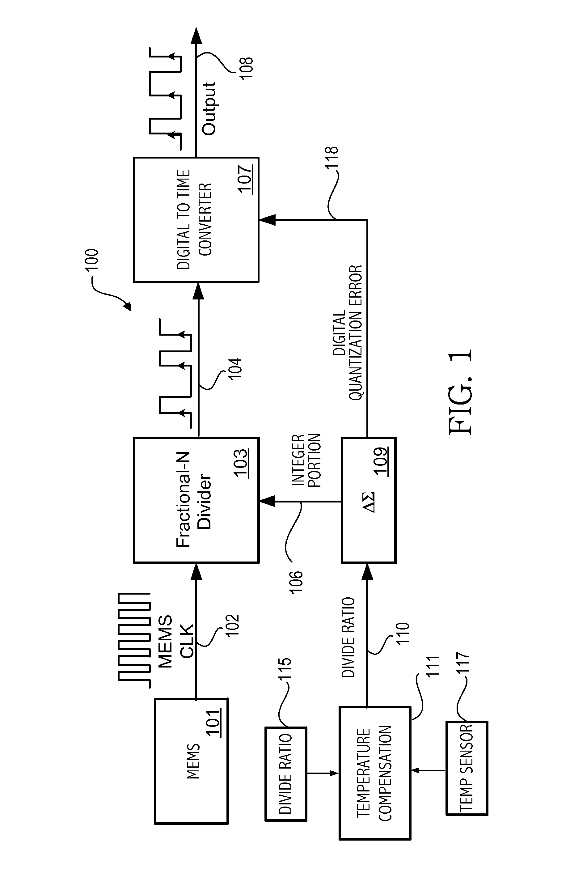
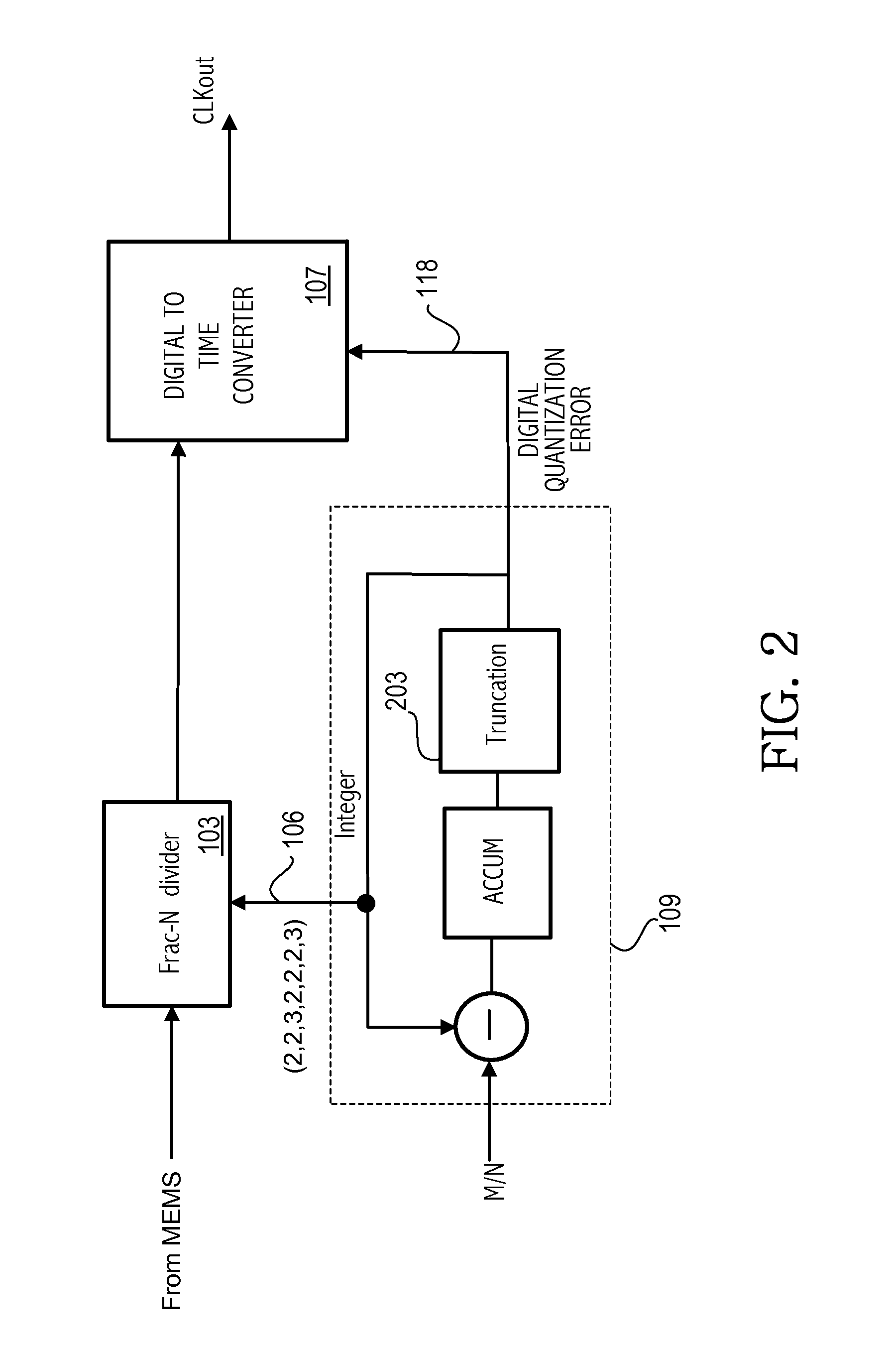
[0015]FIG. 1 illustrates an exemplary system 100. The system includes a MEMS oscillator 101 that supplies a reference clock signal 102. A fractional-N divider 103 receives the MEMS clock signal 102 and divides the MEMS clock signal and supplies the divided signal 104 to a digital-to-time converter (DTC) 107 for phase interpolation to adjust the output of the divider 103. A delta sigma modulator 109 controls the fractional-N divider and generates an integer portion 106, which is used as a divide value by the divider 103. The delta sigma modulator 109 receives a divide ratio 110. Because the MEMS oscillator may be sensitive to temperature variations, a temperature sensor 117 and compensation circuit 111 may be used to adjust the divide ratio 110. The digital divide ratio may be stored in memory 115 associated with compensation circuit 111. The integer portion generated by the delta sigma modulator 109 is supplied to the fractional-N divider 103 as divide control signal 106 in a stream...


PUM


Abstract

A fractional-N divider supplies a divided clock signal. An adjusted divided clock signal is generated in a digital-to-time converter circuit having a delay linearly proportional to digital quantization errors of the fractional-N divider. The adjusted divided clock signal is generated based on first and second capacitors charging to a predetermined level. The charging of the first and second capacitors is interleaved in alternate periods of the divided clock. The charging of each capacitor with a current corresponding to respective digital quantization errors is interleaved with charging with a fixed current. A first edge of a first pulse of the adjusted divided clock signal is generated in response to the first capacitor charging to a predetermined voltage and a first edge of a next pulse of the adjusted divided clock signal is generated in response to the second capacitor charging to the predetermined voltage.

Description

BACKGROUND[0001]1. Field of the Invention[0002]This invention relates to generation of clock signals for electronic devices.[0003]2. Description of the Related Art[0004]Electronics devices utilize clock signals to control operation of, e.g., synchronous digital circuits. Clock signals have commonly been generated using crystal oscillators and phase-locked loops. More recently, digital interpolative synthesis has been utilized as described in U.S. Pat. No. 7,417,510. In such an approach, a reference clock is divided by a fractional-N divider, and jitter introduced by the fractional-N divider is reduced by interpolating the output of the fractional-N divider based on the digital quantization error generated by the delta sigma modulator used to control the fractional-N divider. One approach for the interpolation was to interpolate between various phases of the output from the fractional-N divider in order to reduce jitter. In an alternative approach a half clock reference was used to g...

Claims


Application Information

Patent Timeline
Patent Type & Authority Applications(United States)
IPC IPC(8): H03K5/13
CPCH03K5/131
Inventor WELTIN-WU, COLINHUANG, YUNTENGSETH, MANU
Owner SILICON LAB INC
Learn More