


Quick Research
Generate reliable direction feasibility study reports for your R&D in just a few steps.

Technical Q&A
Discover and master advanced knowledge NOW. Basics, ideas, possibilities, all at once.

Find Solutions
As an expert in R&D theories, this can generate solutions to your technical problems instantly.

Evaluate Feasibility
Analyze your overall solution with one click, know your potential R&D risks in advance.

Monitor Landscape
Get weekly tech updates, stay abreast of the latest tech innovations and key insights.
Vehicle height control device for motorcycle
a technology for controlling devices and motorcycles, which is applied in the direction of cycle equipment, transportation and packaging, cycle, etc., can solve the problems of large occupied space of vehicle height control devices, high cost, and inability to sufficiently reduce vehicle height within a short tim
- Summary
- Abstract
- Description
- Claims
- Application Information
AI Technical Summary
Benefits of technology
Problems solved by technology
Method used
Image

Examples
embodiment 1
FIG. 1 to FIG. 10
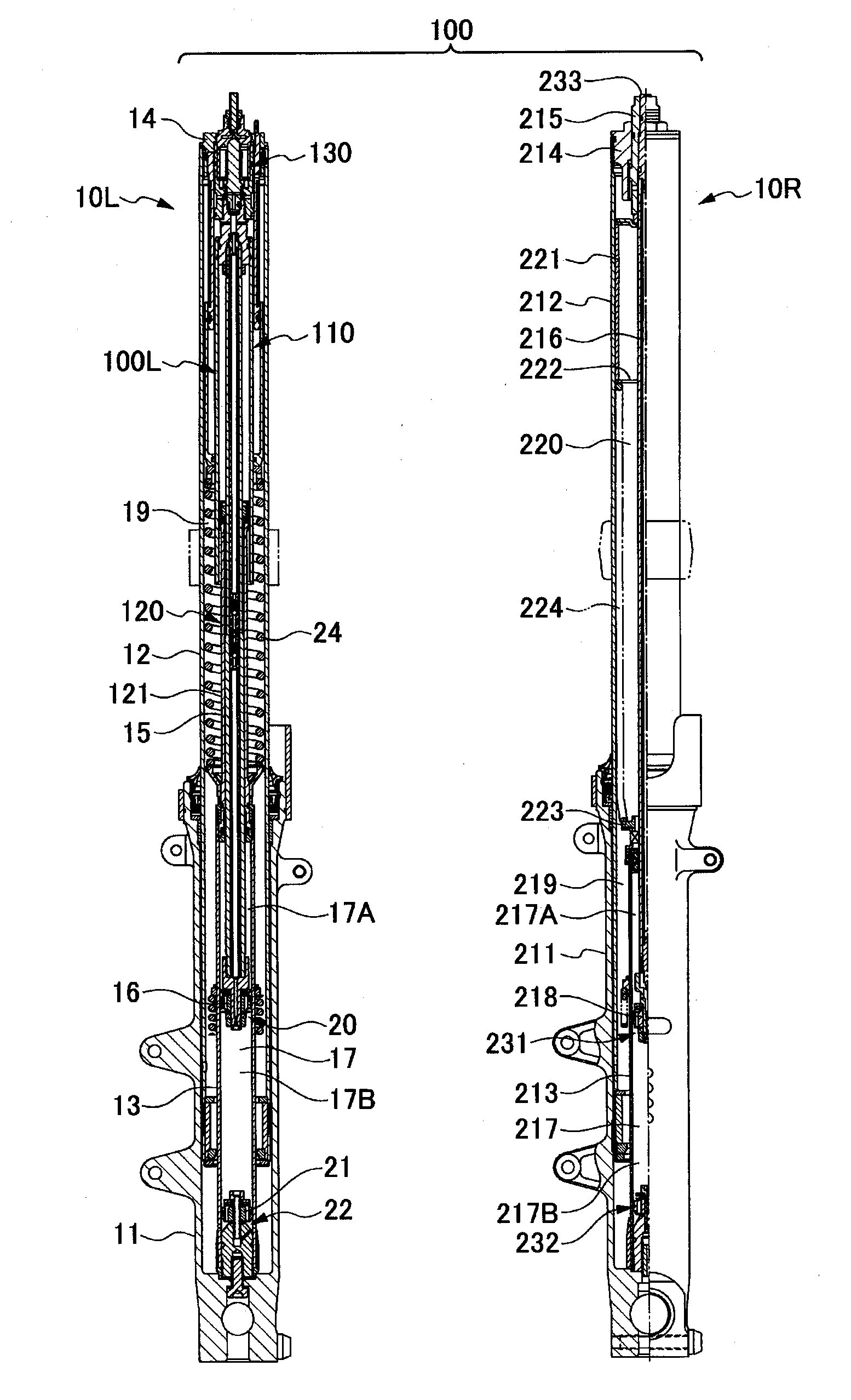
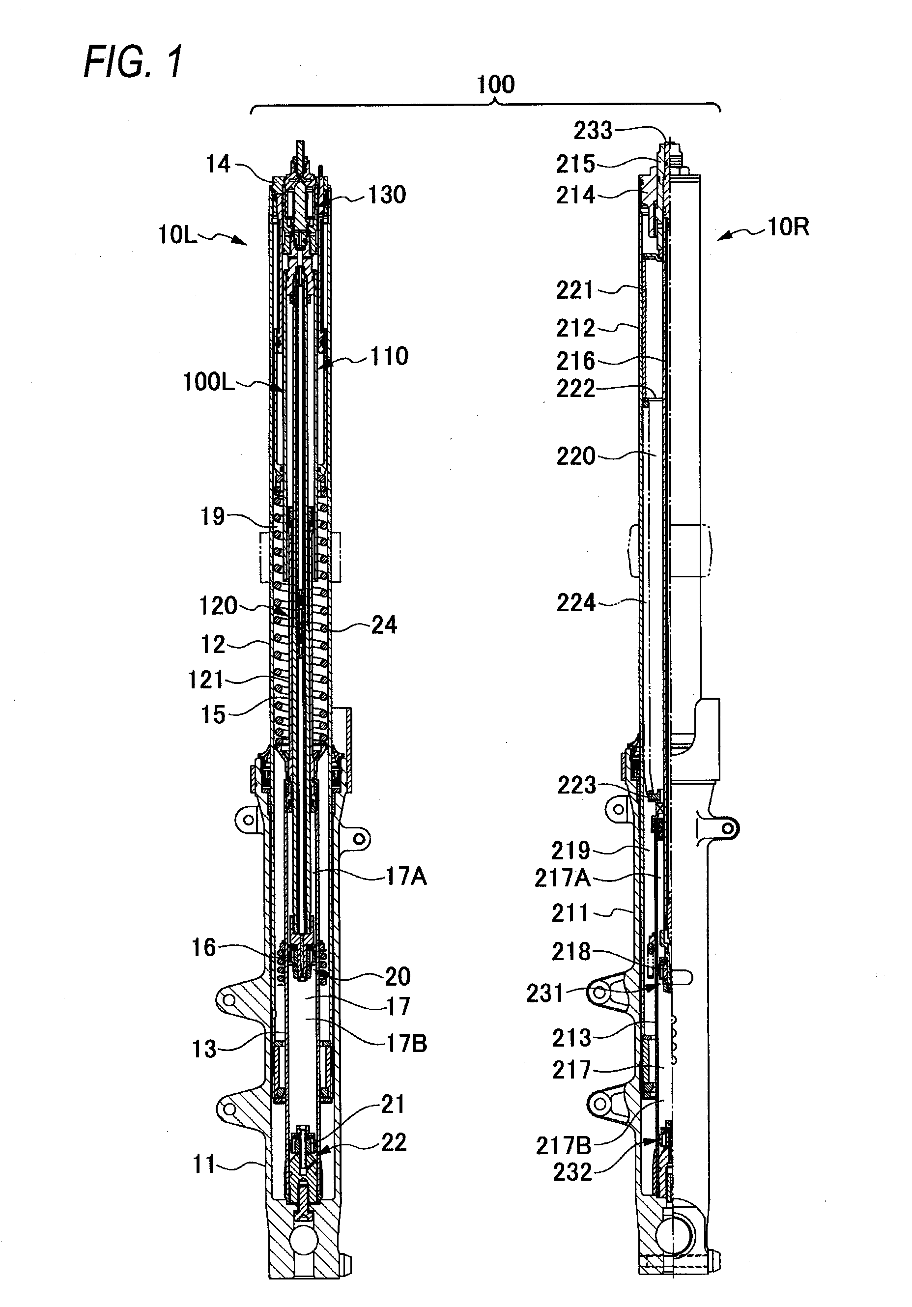
[0046]FIG. 1 shows a pair of dampers 10L and 10R disposed on a left side and a right side, respectively, of a vehicle so as to form a front fork of a motorcycle. In this case, in the motorcycle according to the present embodiment, a vehicle height control device 100 is configured by providing a vehicle height control unit 100L only in one of the left and right dampers, that is, the damper 10L. The damper 10L and the damper 100R will be described below in detail.
[0047](Configuration of the Damper 10L) (FIG. 1 to FIG. 8)
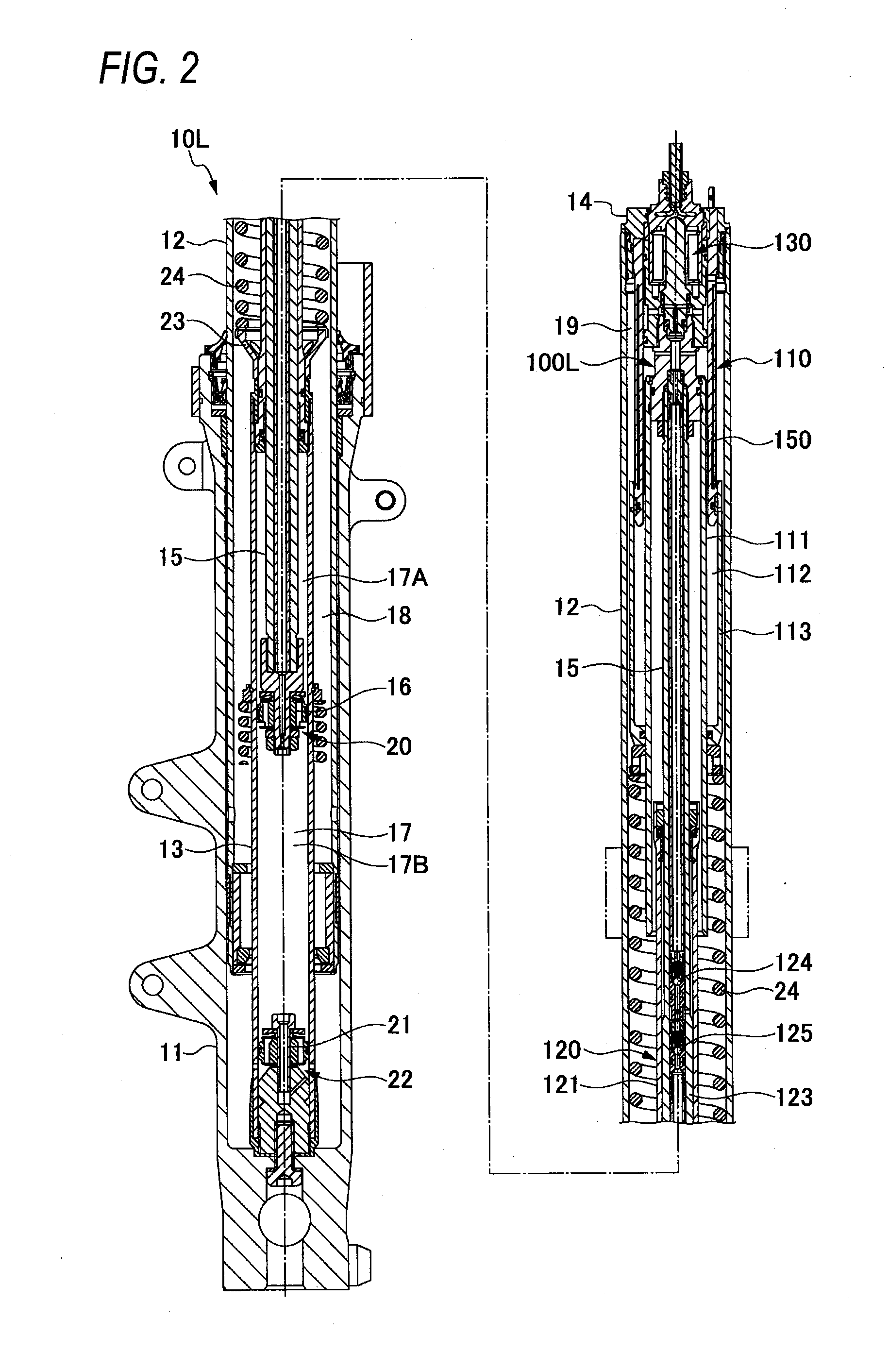
[0048]The damper 10L includes a wheel side tube (outer tube) 11 located on a wheel side and which is closed at one end and which is open at the other end, and a vehicle body side tube (inner tube) 12 located on a vehicle body side and slidably inserted into the wheel side tube 11, so as to form an upright front fork, as shown in FIG. 1 to FIG. 4.
[0049]The damper 100L includes a damper cylinder 13 provided upright in an inner bottom portion of the wheel...
embodiment 2
FIG. 11 to FIG. 15
[0135]FIG. 11 shows a pair of dampers 10L and 10R disposed on a left side and a right side, respectively, of a vehicle so as to form a front fork of a motorcycle. In this case, in a motorcycle according to the present embodiment, a vehicle height control device 100 is configured by providing a vehicle height control unit 100L only in one of the left and right dampers, that is, the damper 100L. The damper 100L and the damper 10R will be described below in detail.
[0136](Configuration of the Damper 100L) (FIG. 11 to FIG. 14)
[0137]The damper 100L includes a wheel side tube (inner tube) 11 located on a wheel side and which is closed at one end and which is open at the other end, and a vehicle body side tube (outer tube) 12 located on a vehicle body side and into which the wheel side tube 11 is slidably inserted, so as to form an upside-down front fork, as shown in FIG. 11 to FIG. 14.
[0138]The damper 10L includes a damper cylinder 13 provided upright in an inner bottom p...
PUM
 Abstract
Description
Claims
Application Information
 - R&D Engineer
- R&D Manager
- IP Professional
- Industry Leading Data Capabilities
- Powerful AI technology
- Patent DNA Extraction
Browse by: Latest US Patents, China's latest patents, Technical Efficacy Thesaurus, Application Domain, Technology Topic, Popular Technical Reports.
© 2024 PatSnap. All rights reserved.Legal|Privacy policy|Modern Slavery Act Transparency Statement|Sitemap|About US| Contact US: help@patsnap.com