
Tracked vehicle

a tracked vehicle and track technology, applied in the superstructure of loading-carrying vehicles, cranes, constructions, etc., can solve problems such as imposing certain limitations on vehicle components, presenting problems or challenges, and work equipment cannot be mounted as readily to the frame of the tracked utility vehicle than to the frame of the truck

Active Publication Date: 2014-06-26
PRINOTH LTD
View PDF27 Cites 18 Cited by
  • Summary
  • Abstract
  • Description
  • Claims
  • Application Information

AI Technical Summary

Benefits of technology

The invention is a tracked vehicle that is designed to carry work equipment and has a unique structure for traction. The vehicle has a frame with a mounting area for the work equipment and an operator cabin with a seating area for the operator. The vehicle also has a power plant and a plurality of track assemblies for traction. The track assemblies are mounted to the frame and each includes a drive wheel, an end wheel, and a plurality of support wheels. The vehicle also has an endless track that engages the ground for traction. The tracked vehicle is designed to have a vehicle height limit for travel on public road infrastructure. The technical effects of the invention include improved efficiency, better maneuverability, and improved safety for the operator.

Problems solved by technology

This typically imposes certain limitations on components of the vehicle.
This can often present issues or challenges.
Since the tracked utility vehicle's frame is typically very different from a truck's frame, the work equipment cannot be mounted as readily to the tracked utility vehicle's frame than to a truck's frame.
Installing the endless track around the set of wheels can sometimes be difficult.
For instance, in some case, the endless track's inner side may have guide projections which may interfere with some of the wheels during installation of the track around the set of wheels.
Also, tension in the endless track may be maintained by an independent tensioner (e.g., a hydraulic accumulator and cylinder or a spring-loaded actuator) which may cause certain issues (e.g., difficulties in maintaining constant tension over displacement of the cylinder or actuator).

Method used


Image

  • Tracked vehicle
  • Tracked vehicle
  • Tracked vehicle

Examples


Embodiment Construction

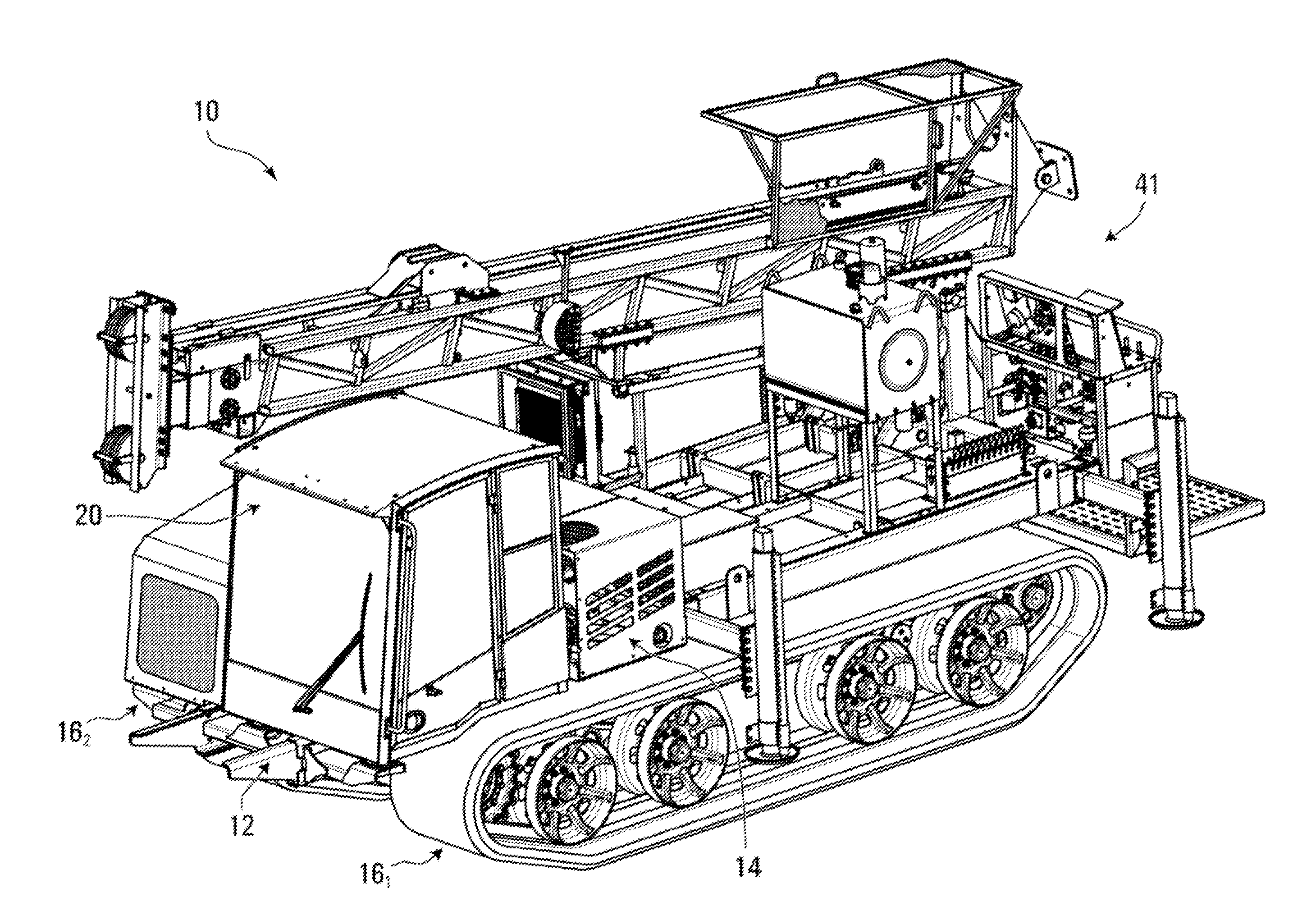
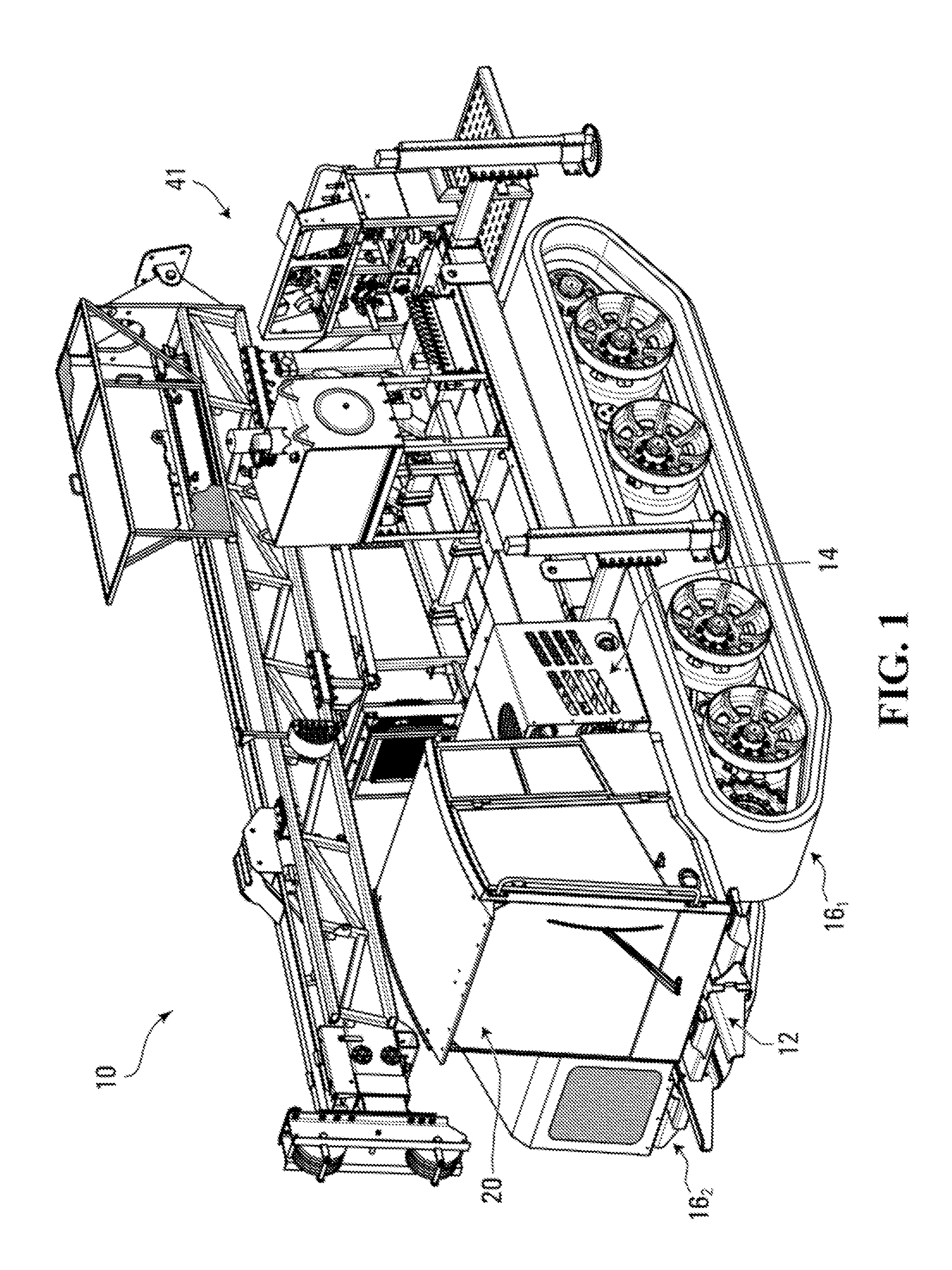
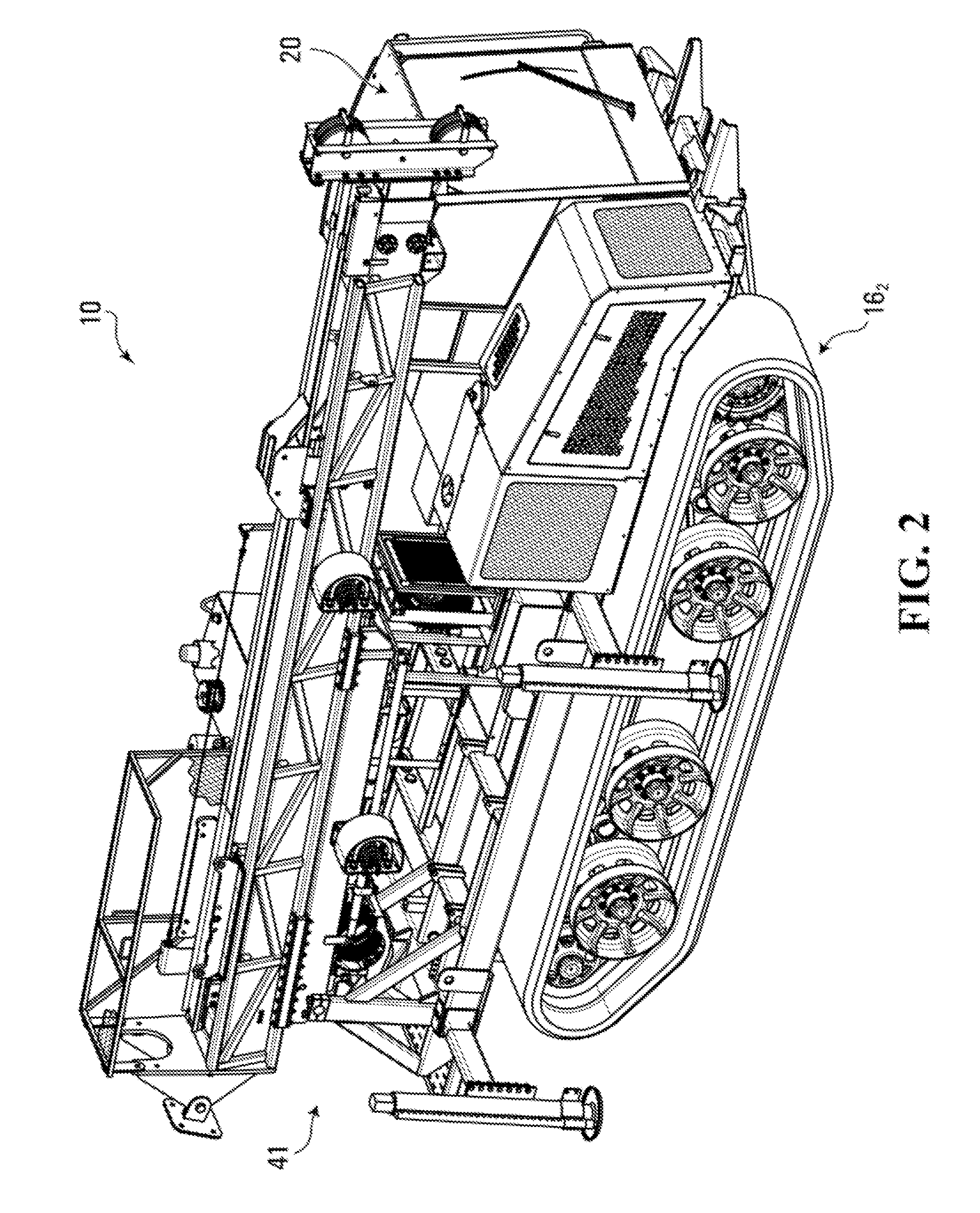
[0042]FIGS. 1 to 13 show an example of a tracked utility vehicle 10 in accordance with an embodiment of the invention. The tracked utility vehicle 10 is designed to carry and enable use of work equipment 41, which includes one or more work implements such as, for example, a crane, a ladder, an aerial device, an aerial work platform, a lift, a drill rig, a digger derrick, a material handler, and / or any other industrial apparatus, on various terrains, including rugged terrain (e.g., with mud, steep hills, swamps, rocks, mud, and / or snow). This type of vehicle can sometimes be referred to as a “tracked carrier” or “tracked equipment carrier” vehicle.

[0043]The tracked utility vehicle 10 has a length Lv, a width Wv, and a height Hv (measured without taking into account the work equipment 41). These dimensions may allow the vehicle 10 to have a large payload capacity while being able to be used in a public road infrastructure. For example, in some embodiments, the length Lv may be at leas...


PUM


Abstract

A tracked vehicle, such as tracked carrier to carry and enable use of work equipment (e.g., a crane, an aerial work platform, a drill rig, etc.) on various terrains, is provided. The tracked vehicle may comprise a frame comprising an equipment mounting area for mounting work equipment above the frame. The frame may comprise a pair of side rails that have a spacing in a widthwise direction of the tracked vehicle which corresponds to a standard truck frame side rail spacing (e.g., 34 inches). An operator cabin comprises a seating area which may comprise a single seat for an operator or a first seat for the operator and a second seat for a second person next to the operator. At least part of a power plant of the tracked vehicle may be mounted above the frame and behind the operator cabin. The tracked vehicle comprises a plurality of track assemblies for traction of the tracked vehicle.

Description

CROSS-REFERENCE TO RELATED APPLICATIONS[0001]This application claims priority from U.S. Provisional Patent Application No. 61 / 529,639 filed on Aug. 31, 2011 and U.S. Provisional Patent Application No. 61 / 542,551 filed on Oct. 3, 2011, both of which are hereby incorporated by reference herein.FIELD OF THE INVENTION[0002]The invention relates to tracked vehicles designed to travel on various terrains, including rugged terrain, and, in particular, to tracked utility vehicles carrying work equipment.BACKGROUND[0003]One type of tracked vehicle is a tracked utility vehicle, sometimes referred to as a “tracked carrier” or “tracked equipment carrier” vehicle, which carries and enables use of work equipment, such as a crane, an aerial device, a drill rig, a digger derrick, and / or any other industrial apparatus, on various terrains, including rugged terrain (e.g., with mud, steep hills, swamps, rocks, mud, and / or snow).[0004]It is often desirable for a tracked utility vehicle to have a carryi...

Claims


Application Information

Patent Timeline
IPC IPC(8): B62D55/06
CPCE02F9/16B62D55/06B66C23/44B62D55/14B62D33/06B62D55/12B62D55/08B62D55/244
Inventor STEBEN, ERICMARLEAU, BENOIT
Owner PRINOTH LTD
Learn More