
Method and System for Inspecting a Surface Area for Material Defects

a technology of surface area and inspection method, which is applied in the direction of television system, process and machine control, instruments, etc., can solve the problems of large effort required for inspection of material defects, serious static impairment, and negative effects of material defects on the stability of components of structures, so as to reduce the associated effort and safety risk

Active Publication Date: 2014-06-19
EADS DEUT GMBH
View PDF4 Cites 218 Cited by
  • Summary
  • Abstract
  • Description
  • Claims
  • Application Information

AI Technical Summary

Benefits of technology

The present invention provides a method and system for inspecting surfaces for material defects that reduces effort and safety risks.

Problems solved by technology

Material defects may have negative effects on the stability of components of structures such as bridge pillars or rotor blades of wind turbines.
Material defects may propagate and lead to serious static impairments.
In the case of surfaces that are difficult to reach and / or are at a great height (such as the blades of offshore wind turbines, for example), an inspection for material defects requires great effort because people must be lowered by cable from a great height to be able to reach the surfaces to be inspected, for example, and then to inspect them.

Method used


Image

  • Method and System for Inspecting a Surface Area for Material Defects
  • Method and System for Inspecting a Surface Area for Material Defects
  • Method and System for Inspecting a Surface Area for Material Defects

Examples


Embodiment Construction

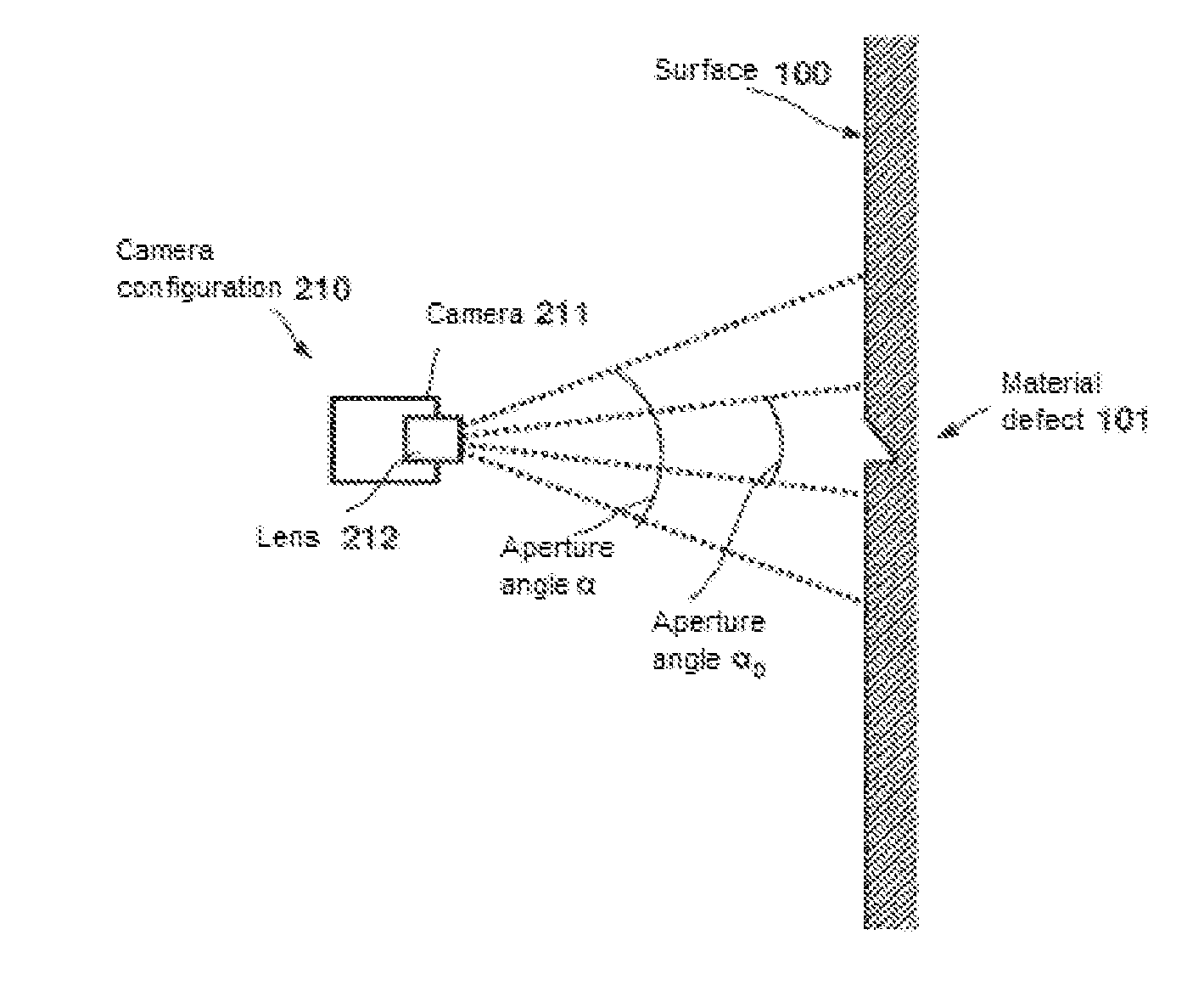
[0013]FIG. 1 shows a front view of any surface 100. The surface 100 is, for example, a surface that is difficult to access, for example, being located at a great height. This surface 100 may have material defects 101. The material defect 101 illustrated in FIG. 1 may be a crack, for example. According to the invention, at least one first image 121 of the surface 100 to be inspected is recorded. In practice, however, it will often occur that the surface 100 is too large to be detected with sufficient image quality by a single image 121, in particular when the image is recorded by a camera using a telescopic lens. Therefore at least one second image 122 or a sequence 120 of images may be recorded, each representing individual surface sections of the surface 100.

[0014]If at least one second image 122, i.e., a sequence 120 of images, is necessary, then the individual images 121, 122 of the sequence 120 may be recorded in such a manner that neighboring images in the overlap regions 123 o...


PUM

PropertyMeasurementUnit
fixed angleaaaaaaaaaa
diametersaaaaaaaaaa
heightsaaaaaaaaaa

Abstract

A camera assembly arranged on an unmanned and autonomously navigating aerial vehicle is employed to inspect a surface area of for material defects. The vehicle is automatically flown to the surface area from a launch site, wherein it can fly around obstacles using automatic obstacle detection and avoidance methods. A relative position of the aerial vehicle with respect to the surface area with the aid of a position sensor is continuously measured and a sequence of images of the surface area is recorded. Between the individual images, the aerial vehicle is moved along a flight path overlapping image details of the surface area. The images of the sequence are composed into an overall image of the surface area to allow for the surface area to be inspected for defects and the location of defects to be ascertained on the basis of the overall image.

Description

BACKGROUND AND SUMMARY OF THE INVENTION[0001]Exemplary embodiments of the present invention relate to a method and a system for automated inspection of a surface for material defects.[0002]Material defects may have negative effects on the stability of components of structures such as bridge pillars or rotor blades of wind turbines. Material defects may propagate and lead to serious static impairments. The surfaces of such structures are therefore usually subjected to regular inspections, in particular visual inspections. In the case of surfaces that are difficult to reach and / or are at a great height (such as the blades of offshore wind turbines, for example), an inspection for material defects requires great effort because people must be lowered by cable from a great height to be able to reach the surfaces to be inspected, for example, and then to inspect them. The time required to do so is particularly important but the safety aspect is also significant.[0003]Exemplary embodiments...

Claims


Application Information

Patent Timeline
Patent Type & Authority Applications(United States)
IPC IPC(8): G01N21/88
CPCG01N21/88G05D1/0094G01M5/0016G01M5/0033G01M5/0075G01M5/0091G01C11/02Y02B10/30F03D17/00F03D80/50G01N25/72Y02E10/72B64U2101/30B64U2201/10B64U2101/26
Inventor NADERHIRN, MICHAELLANGTHALER, PETER
Owner EADS DEUT GMBH
Learn More