Chute for optical sorting machine

a sorting machine and chute technology, applied in the direction of chutes, sorting, transportation and packaging, etc., can solve the problems of unfavorable detection of defective articles, unclean chute surface, and inability to detect defective articles, so as to prevent unfavorable sorted articles from falling off and clean easily

Inactive Publication Date: 2014-06-19
SATAKE CORP
View PDF0 Cites 25 Cited by
  • Summary
  • Abstract
  • Description
  • Claims
  • Application Information

AI Technical Summary

Benefits of technology

[0021]According to the chute of the present invention, since sorted articles disperse due to the impacts in their movements from the flat surface that positions on the upstream side to the flat surface that positions on the downstream side, unevenness of the flow of the sorted articles on the chute surface can be prevented.
[0022]Moreover, since, in the first part of the chute according to the present invention, smooth undulations are formed on the surface which the sorted articles flow down and the sorted articles move between the plurality of flat surfaces with moderate impacts, hops of the sorted articles hardly arise on the first part.
[0023]Furthermore, in the chute according to the present invention, since the first part is composed of one component and the continuity of the component is maintained, deposition of powdery dusts does not arise on the first ...

Problems solved by technology

Incidentally, in the above-mentioned optical sorting machine, when the raw material is granular articles with long and thin shapes such as long grain rice, granular articles with viscosity on the surfaces such as parboiled rice, or the like, the plural granular articles overlapping with and/or being joined to one another are liable to cause unevenness of the flow of the granular articles on the chute surface.
As a result, there has been a problem that failure in detection of defective articles and the like, and/or failure in exclusion, for example, exclusion of good articles mixed up with the defective articles c...

Method used


Image

  • Chute for optical sorting machine
  • Chute for optical sorting machine
  • Chute for optical sorting machine

Examples


Embodiment Construction

[0041]Embodiments according to the present invention will be described with reference to the drawings.

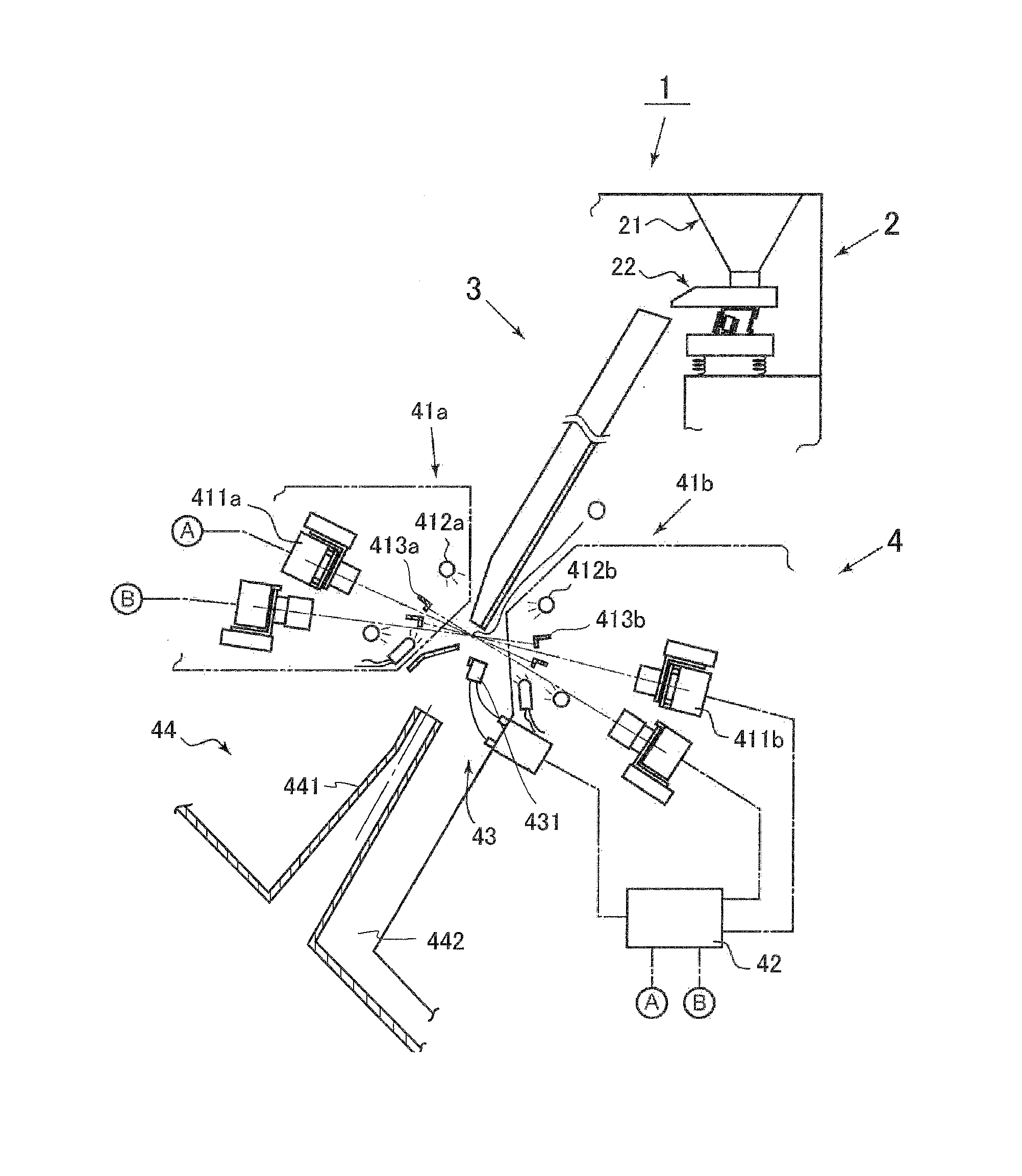
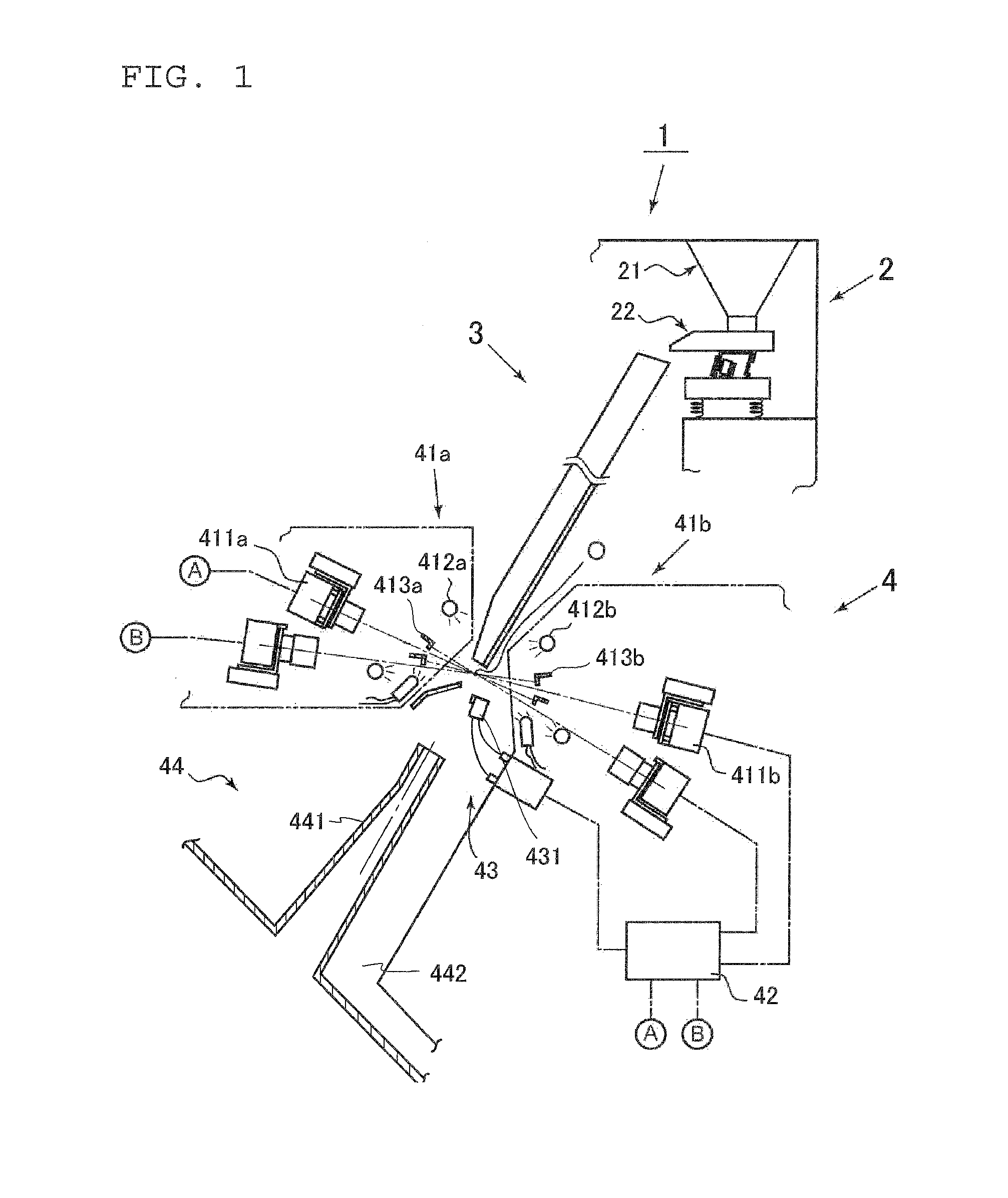
[0042]FIG. 1 is one example of an optical sorting machine using a chute according to the present invention and shows a simplified lateral cross-sectional view of the internal structure of the optical sorting machine.

[0043]An optical sorting machine 1 shown in FIG. 1 includes a granular article feeding part 2, a chute 3 and an optical sorting part 4.

[0044]The granular article feeding part 2 is disposed in the upper part of the optical sorting machine 1 and includes a tank 21 and a vibratory feeder 22 for feeding granular articles in the tank 21.

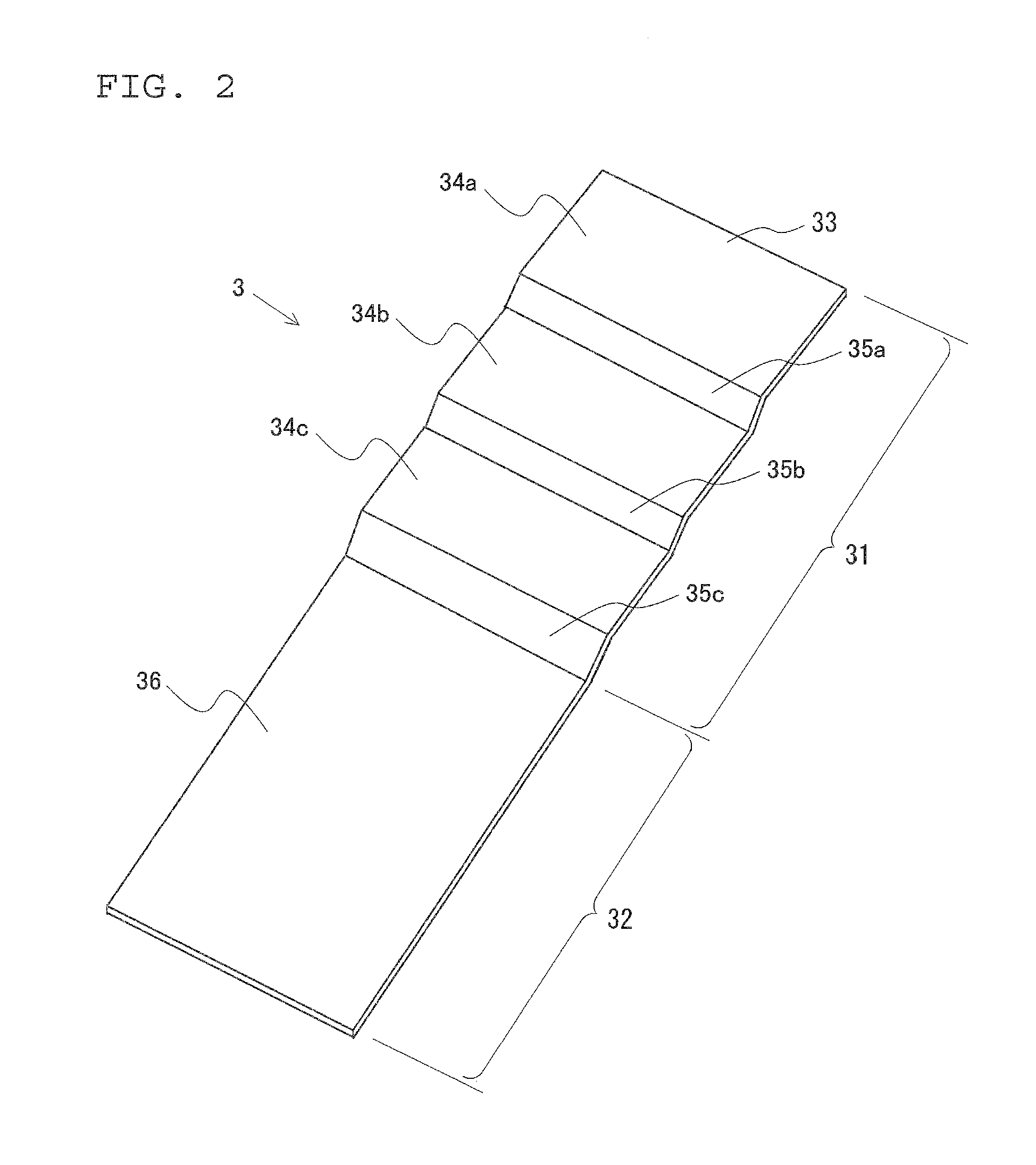
[0045]The chute 3 has a predetermined width and is disposed inclining on the downside of the granular article feeding part 2.

[0046]A large amount of granular articles continuously fed from the vibratory feeder 22 of the granular article feeding part 2 continuously flow down the surface of the chute 3 on the basis of the action of gravity, spre...


PUM


Abstract

A chute for an optical sorter sorting machine allows objects to be sorted to drop under gravity from the lower end of the chute, thereby supplying the objects to an optical detection section. The chute is provided with: a first portion which includes a portion for receiving the objects to be sorted which are supplied from a supply section; and a second portion which continues from the first portion The first portion is composed of a single part and has: flat surfaces along which the objects to be sorted flow down; and connection surfaces. The flat surfaces located upstream are bent downward, and the connection surfaces located downstream are is bent upward to form a smooth undulation in the surface along which the objects to be sorted flow down.

Description

TECHNICAL FIELD [0001]The present invention relates to an optical sorting machine for sorting out granular articles such as grains and plastic pellets on the basis of colors or the like, and particularly relates to a chute used for the optical sorting machine.BACKGROUND ART [0002]Conventionally, an optical sorting machine is known for sorting out raw material composed of grains such as rice, barley, wheat, oats, beans and nuts, plastic pieces such as pellets and beads, fine articles such as drugs, ores and volcanic soil, or other granular articles into good articles or defective articles and / or excluding foreign objects and the like contaminating the raw material.[0003]Optical sorting machines of this kind include one of the type in which a chute with a predetermined width is inclined and disposed on the downside of a granular article feeding part.[0004]The optical sorting machine sorts out the granular articles by: feeding a large amount of granular articles to the chute having the...

Claims


Application Information

Patent Timeline
IPC IPC(8): B65G11/02B07C5/342
CPCB07C5/342B65G11/023B07C5/02B07C5/3425B07C2501/0018B65G11/083B65G11/00
Inventor ITO, TAKAFUMIMIYAMOTO, TOMOYUKI
Owner SATAKE CORP
Why Eureka
Try Eureka