Eureka AIR delivers breakthrough ideas for toughest innovation challenges, trusted by R&D personnel around the world.

Bidirectional unisolated dc-dc converter based on cascaded cells

a cascaded cell, bidirectional technology, applied in the direction of dc-dc conversion, dc-dc conversion, ac conversion apparatus without intermediate, etc., can solve the problems of transformer incurring extra costs and additional power loss, and achieve the effect of eliminating harmonic interaction and eliminating harmonic interaction

Active Publication Date: 2014-06-12
HITACHI ENERGY SWITZERLAND AG
View PDF11 Cites 9 Cited by
  • Summary
  • Abstract
  • Description
  • Claims
  • Application Information

AI Technical Summary

Benefits of technology

The invention is a converter that allows for the efficient transfer of power between multiple voltage sources. It achieves this by circulating an alternating current between the phase legs, which are made up of controllable voltage sources. The converter maintains a constant phase difference between the alternating currents of the phase legs, which reduces harmonic interaction with the DC voltages and allows for a higher power rating. The phase difference between adjacent phase legs is chosen to be 2π / n, where n is the number of phase legs in the converter. This results in a symmetric multi-phase converter that eliminates harmonic interaction and eliminates the need for an AC filter.

Problems solved by technology

However, due to the transformer, such solutions suffer from additional power losses.
Further, the transformer incurs extra costs.

Method used


Image

  • Bidirectional unisolated dc-dc converter based on cascaded cells
  • Bidirectional unisolated dc-dc converter based on cascaded cells
  • Bidirectional unisolated dc-dc converter based on cascaded cells

Examples


Embodiment Construction

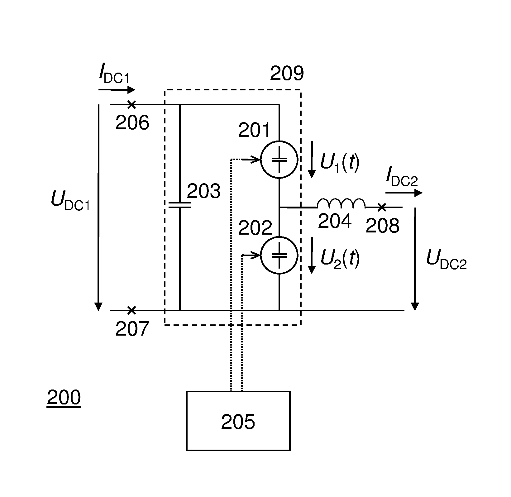
[0035]With reference to FIG. 2, a DC-DC converter in accordance with an embodiment of the invention is described.

[0036]DC-DC converter 200 comprises two variable voltage sources 201 and 202 connected in series, a capacitor 203 connected in parallel to the series-connection of voltage sources 201 and 202, as well as an AC filter 204, in FIG. 2 illustrated as an inductance. AC filter 204 may, e.g., be a reactor. Further, converter 200 comprises a control unit 205, for controlling variable voltage sources 201 and 202, i.e., for controlling the voltage U1(t) and U2(t) provided by 201 and 202, respectively. The operation of voltage sources 201 and 202 is elucidated further below. DC voltage UDC1 and DC current IDC1 are provided to circuitry connected to the high-voltage side of converter 200, i.e., to terminals 206 and 207, and DC voltage UDC2 and DC current IDC2 are provided to the low-voltage side of converter 200, i.e., to terminals 208 and 207. UDC1 is provided in parallel to the ser...


PUM


Abstract

A DC-DC converter (200) comprising a first (201) and a second (202) variable voltage source, a capacitor (203), an alternating current filter (204), and controlling means (205), is provided. A first DC voltage (UDC1) is provided over a series-connection of the first and the second voltage source, and a second DC voltage (UDC2), being lower in magnitude than (UDC1), is provided over the second voltage source. The conversion between (UDC1) and (UDC2) is effected by circulating an alternating current within a circuit comprising the two voltage sources and the capacitor, thereby exchanging power between the two voltage sources. The alternating current is driven by AC voltage components provided by the first and the second voltage source. The controlling means is arranged for controlling the first and the second voltage source so as to maintain a phase difference between the AC components to be close to π.

Description

FIELD OF THE INVENTION[0001]The invention relates in general to power electronic converters for high voltage direct current (HVDC) power transmission and distribution, as well as railway traction systems. More specifically, the invention relates to unisolated, i.e., galvanically not isolated, DC-DC converters employing several series-connected converter modules.BACKGROUND OF THE INVENTION[0002]In order to reduce the harmonic distortion of the output voltage of power electronic converters, so called multilevel converters based on cell strings, providing an output voltage which may assume several discrete levels, have been proposed. A cell string typically comprises a plurality of series-connected converter cells, where each cell contains a number of switching elements, e.g., transistors, and an energy storage element in form of a capacitor, connected either in a half-bridge or a full-bridge type arrangement.[0003]A converter for converting between direct current (DC) voltages is here...

Claims


Application Information

Patent Timeline
Patent Type & Authority Applications(United States)
IPC IPC(8): H02M3/07
CPCH02M3/07H02M3/158H02J3/36Y02E60/60H02M7/4835H02M1/0095H02M7/00H02M3/28
Inventor NORRGA, STAFFAN
Owner HITACHI ENERGY SWITZERLAND AG
Why Eureka
Eureka Blog
Learn More