Concentric co-extrusion die and a method of extruding a multilayer thermoplastic film

a thermoplastic film and concentrate technology, applied in the direction of dough shaping, synthetic resin layered products, applications, etc., can solve the problems of increasing melt temperatures and material degradation, complex internal construction of dies, and the size of dies that cannot reduce the thickness of specific layers, so as to improve the thickness tolerance

Active Publication Date: 2014-06-12
PLASTIKA KRITIS
View PDF6 Cites 3 Cited by
  • Summary
  • Abstract
  • Description
  • Claims
  • Application Information

AI Technical Summary

Benefits of technology

[0037]It is also possible to have different materials for each of the extruders supplying the mandrel, resulting in different properties around the circumference of the film and resulting bubble.
[0038]Another possibility is to improve the thickness tolerance by controllin...

Problems solved by technology

As can be seen, such dies have complex internal constructions, requiring the accurate registration of components in the different layers.
As a consequence, higher melt pressures are developed in use and the material residence time gets longer, resulting in increased melt temperatures and material degradation.
In addition the size of the die does not allow reducing the thickness of a specific layer while maintaining good thickness uniformity of this layer due to the very long paths that the melt has to flow though within the die and the required low material quantity for such layer.
Further, the back pressure developed between the layer inlet and the start of the helical outlet ...

Method used


Image

  • Concentric co-extrusion die and a method of extruding a multilayer thermoplastic film
  • Concentric co-extrusion die and a method of extruding a multilayer thermoplastic film
  • Concentric co-extrusion die and a method of extruding a multilayer thermoplastic film

Examples


Embodiment Construction

IN ACCORDANCE WITH THE INVENTION

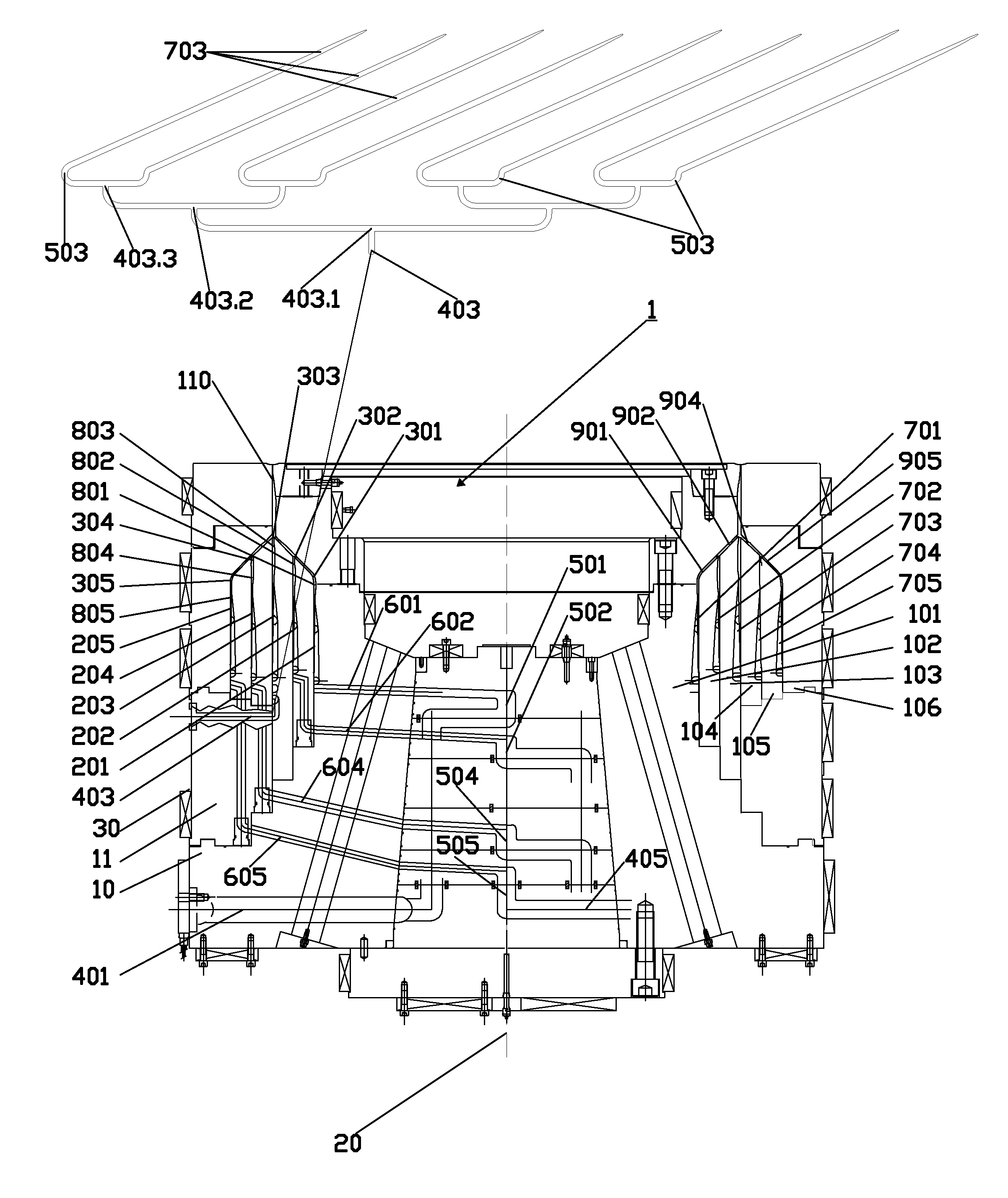
[0053]In the examples described below, the mandrel exit diameter is shown to be 1800 mm. However co-extrusion dies according to the present invention can have any desired exit diameter, but are especially suitable for diameters in the range of 1300 to 2500 mm. The detailed design of all parts depends on the final application as well as required residence time, pressure and other rheological parameters.

[0054]In the deextruders, total number of layers, number of layers which are side fed with multiple inlets, number of inlets per layer, number of bifurcations, number of spirals overlaps, number of spirals, number of radial ports, inclination of ports, inclination of side feed inlets etc) are indicative and only for the purpose of the examples.

[0055]In FIG. 4, a longitudinal section of a first concentric co-extrusion die is shown as well as a developed partial annular section of the middle layer. The co-extrusion die 1 has six concentric mandrels 101-106...


PUM

PropertyMeasurementUnit
Lengthaaaaaaaaaa
Lengthaaaaaaaaaa
Circumferenceaaaaaaaaaa

Abstract

A large concentric co-extrusion die (1) is described having a plurality of annular or conical die mandrel layers (201-205). Each layer is formed between a pair of adjacent annular or conical die mandrels (101-106) defining between them a flow path for molten thermoplastics material from an inlet to an annular extrusion outlet (110) through which a thermoplastics tubular extrusion is formed in use. Extrusion takes place through the multiple annular layer outlets (301-305) to form a multi-layered product. At least one layer (203) of the annular or conical die mandrels has a plurality of molten material inlets arranged around the external circumference of the co-extrusion die with each inlet being connected to a feed channel (403) which has plural bifurcations (403.1, 403.2, 403.3) providing 2n subsidiary outlet feed channels (503) where n is the number of bifurcations. Each subsidiary outlet feed channel being connected to a corresponding helical outlet channel (703).

Description

[0001]The present invention relates to extrusion dies and, more particularly, to co-extrusion dies and especially those for extruding large width blown films using thermoplastic materials.BACKGROUND[0002]The basic function of any blown film extrusion die is to take one or more melt streams entering the die and distribute them to a single concentric annular melt stream at the die exit as uniformly as possible.[0003]A number of different types of extruder die are known in the art. Concentric helical mandrel dies are cylindrical in shape and are mounted one above another secured to a common component to maintain their relative positions. Variations of this design may have, for example, a central feed where all melt streams are fed to the centre and then split to the helical outlet channels with radially arranged tubular ports. An example of this type is shown in U.S. Pat. No. 3,966,377. Another variation is an annular feed mandrel die in which the melt streams flow into the die through...

Claims


Application Information

Patent Timeline
IPC IPC(8): B29C47/26B29C47/06B29C48/10B29C48/21B29C48/335B29C48/495
CPCB29C47/0026B29C47/065B29C47/263B29C47/364B29C47/268B29C47/56B29C47/70B29C47/265B29C48/10B29C48/3366B29C48/30B29C48/49B29C48/21B29C48/338B29C48/695B29C48/3363B29C48/37B29C48/336B29C48/705B29C48/495B29C48/18B29C48/335
Inventor LEMPIDAKIS, EMMANOUILMELAS, IOANNISKALARAKIS, MINAS
Owner PLASTIKA KRITIS
Why Eureka
Try Eureka