
Vehicular HVAC system with modified air recirculation for start-stop engine

Active Publication Date: 2014-06-12
FORD GLOBAL TECH LLC
View PDF15 Cites 17 Cited by
  • Summary
  • Abstract
  • Description
  • Claims
  • Application Information

AI Technical Summary

Benefits of technology

The invention helps engines stop for longer periods of time by identifying conditions where a full recirculation position can be used without causing an increase in fogging.

Problems solved by technology

If the cabin temperature increases by a certain amount, the engine is usually restarted so that cooling resumes, but some of the fuel economy improvement may be lost.
However, cold storage devices are expensive, are difficult to package due to their larger size, and require additional controls.
Moreover, since they consume additional energy during engine operation, the fuel economy improvement is lessened.
In a typical gasoline-powered vehicle, however, the expense of such an auxiliary air conditioning system is usually prohibitive.
Even in a hybrid vehicle (i.e., having both a combustion engine and an electric propulsion system), the additional use of the electric compressor would result in the loss of fuel economy.
It discloses that if the air entering the HVAC is not managed carefully, fuel economy and battery consumption may not be optimized.
Particularly, if the fresh air mode is selected as the source of air for the HVAC system in hot weather, this air mode will add more cooling load to the compressor and increase energy consumption.
On the other hand, if the fresh air mode is selected as the source of air for the HVAC system in cold weather, this air mode will slow down heater / defrost performance.
A further complication is that when the full recirculation mode is selected, window fogging may result in certain ambient conditions.
However, it would be undesirable to allow any fogging of the windows to occur during an auto stop event of the engine.

Method used


Image

  • Vehicular HVAC system with modified air recirculation for start-stop engine
  • Vehicular HVAC system with modified air recirculation for start-stop engine
  • Vehicular HVAC system with modified air recirculation for start-stop engine

Examples


Embodiment Construction

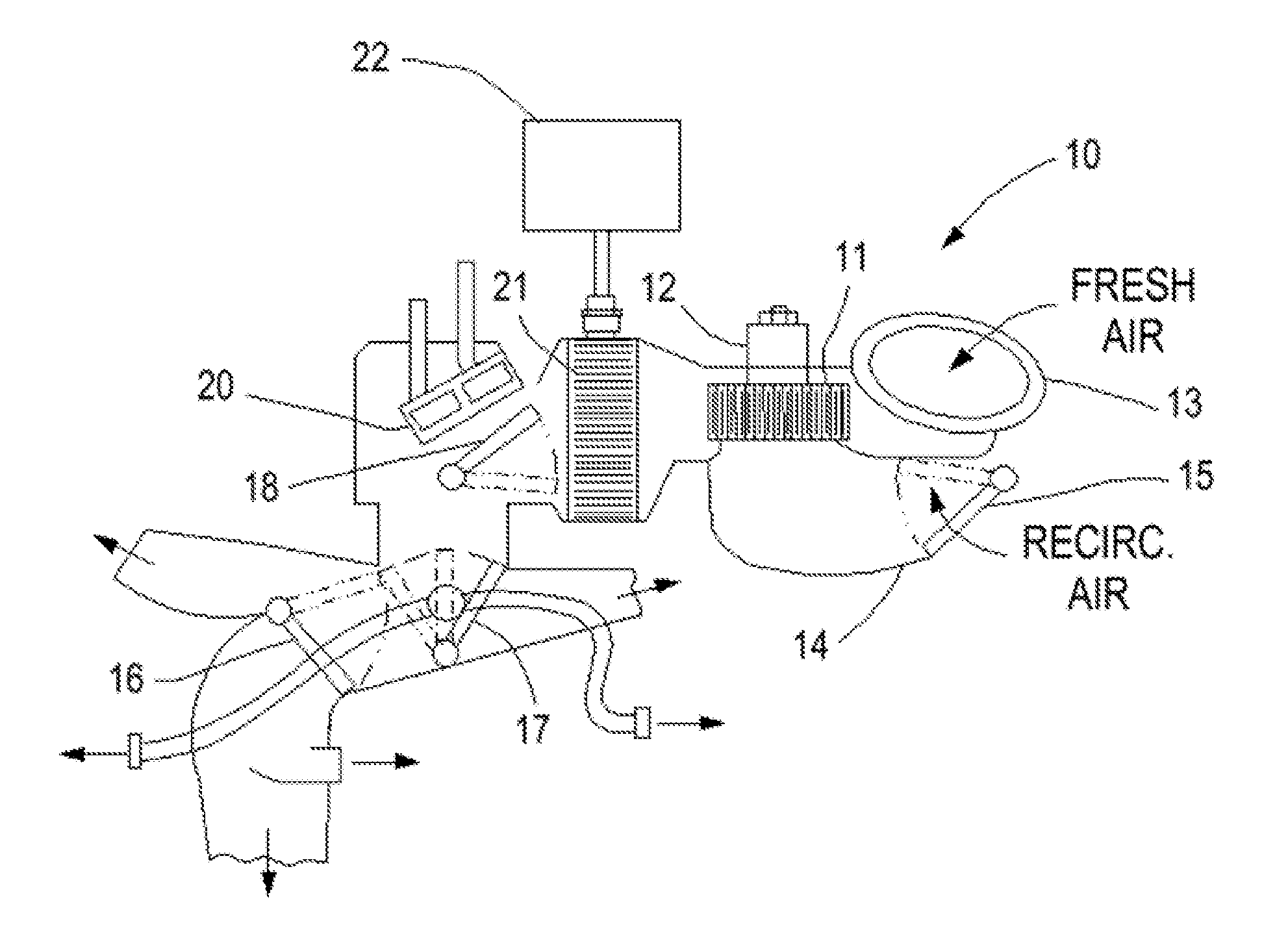
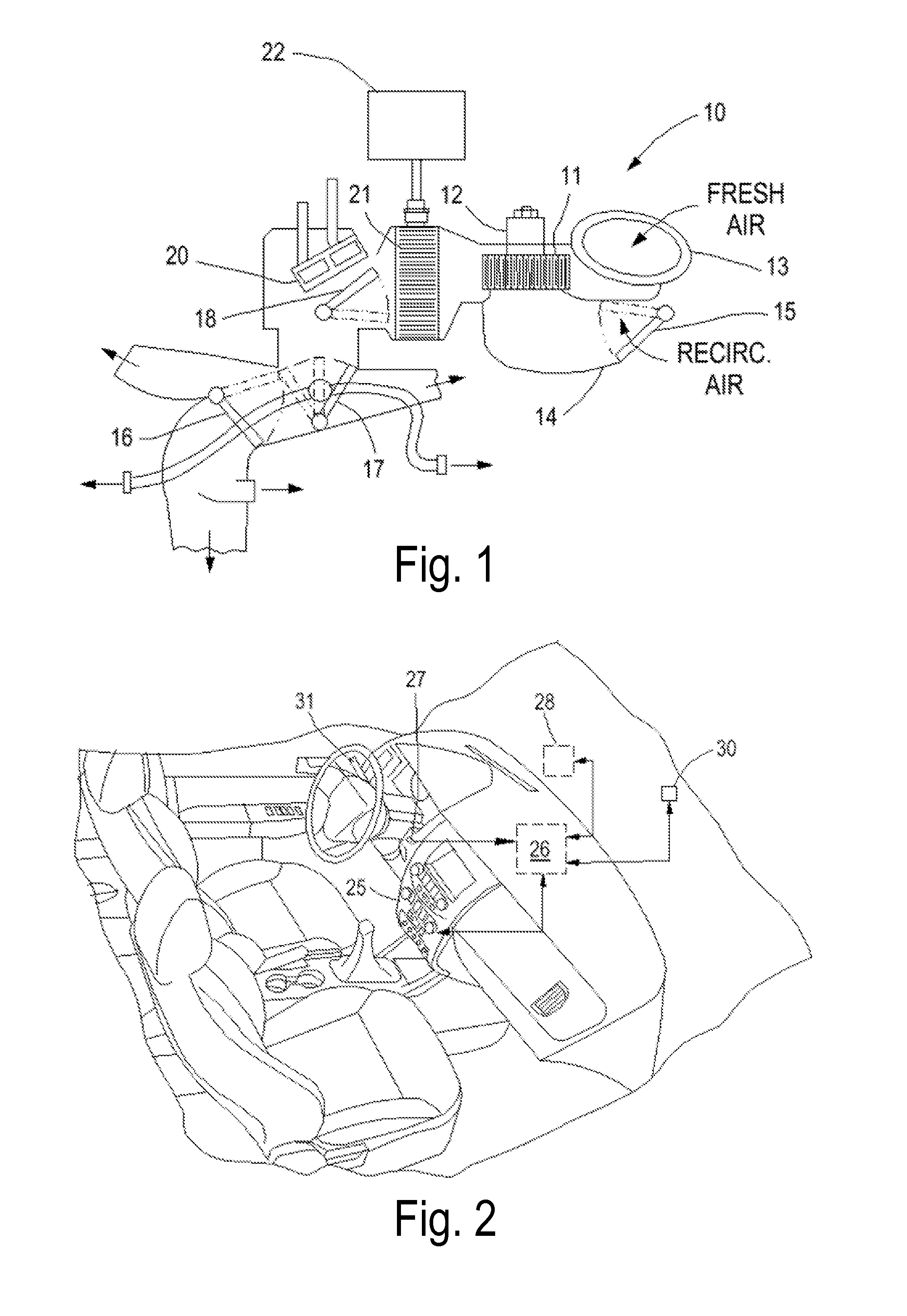
[0018]FIG. 1 shows schematically an air handling system of a heating, ventilation and air conditioning (HVAC) system 10. A blower 11 driven by a blower motor 12 receives inlet air comprised of fresh air from a duct 13 and / or recirculated air from a cabin air return vent 14 as determined by a recirculation door 15. System 10 also includes a panel-defrost door 16, a floor-panel door 17, and a temperature blend door 18. Door 15 functions to regulate air passing to the inlet of blower 11 between fresh air and recirculated air. As used herein, a partial recirculation setting may be expressed as a percentage opening of door 15 (i.e., the proportional share of inlet air that is being recirculated). Thus, a higher percentage indicates a greater amount of recirculated air. Other known air flow regulating devices may be used instead of the illustrated door configuration.

[0019]The various doors are driven by any of several types of actuators (including, for example and without limitation, elec...


PUM


Abstract

A method controls a recirculation position of a return vent in an HVAC system for a vehicle with a compressor driven by a start / stop engine. A partial s recirculation position is set according to a basic recirculation strategy while the engine is operating. An auto stop event is entered at a time with the compressor operating. A full recirculation position is set during the stop event if a plurality of low fogging probability indicators are true. The low fogging probability indicators include a sensed ambient temperature being above a predetermined temperature, a sensed state of a windshield wiper being an off state, and a sensed sunload being above a predetermined sunload.

Description

CROSS REFERENCE TO RELATED APPLICATIONS[0001]Not Applicable.STATEMENT REGARDING FEDERALLY SPONSORED RESEARCH[0002]Not Applicable.BACKGROUND OF THE INVENTION[0003]The present invention relates in general to automatic control of fresh or recirculated air flow into a vehicular heating, ventilating, and air conditioning (HVAC) system. More specifically, the invention relates to controlling recirculated air flow to improve efficiency for an internal combustion (IC) vehicle having start / stop capability by increasing IC engine off time.[0004]Fuel economy of automobiles is an important attribute of vehicle performance which is determined by the technologies employed in the vehicle design, by driver behavior and actions, and by conditions under which the vehicle is used (e.g., speed, road design, weather, and traffic). Manufacturers continuously strive to deliver better fuel economy. One technology being increasingly used is known as automatic[0005]Start-Stop technology, wherein an internal ...

Claims


Application Information

Patent Timeline
IPC IPC(8): F25B41/00
CPCF25B41/00F25B27/00F25B49/022F25B2327/001F25B2600/0251F25B2700/2106B60H1/0075B60H1/00778B60H1/00785B60H1/00849
Inventor PEBLEY, KIRK R.MADHAVAN, RANGANATHANSCHAEFER, ERIC G.KOBERSTEIN, MANFREDROLLINSON, JAMES C.
Owner FORD GLOBAL TECH LLC
Learn More