
Observation device with range finder

a technology of optical devices and range finders, applied in the field of long-range optical devices, can solve the problems of not having the desired ergonomics, requiring a rotating screen driven by a motor, and affecting the user's experience, and achieve the effect of increasing user-friendliness

Active Publication Date: 2014-06-05
SWAROVSKI-OPTIK AG & CO KG
View PDF2 Cites 0 Cited by
  • Summary
  • Abstract
  • Description
  • Claims
  • Application Information

AI Technical Summary

Benefits of technology

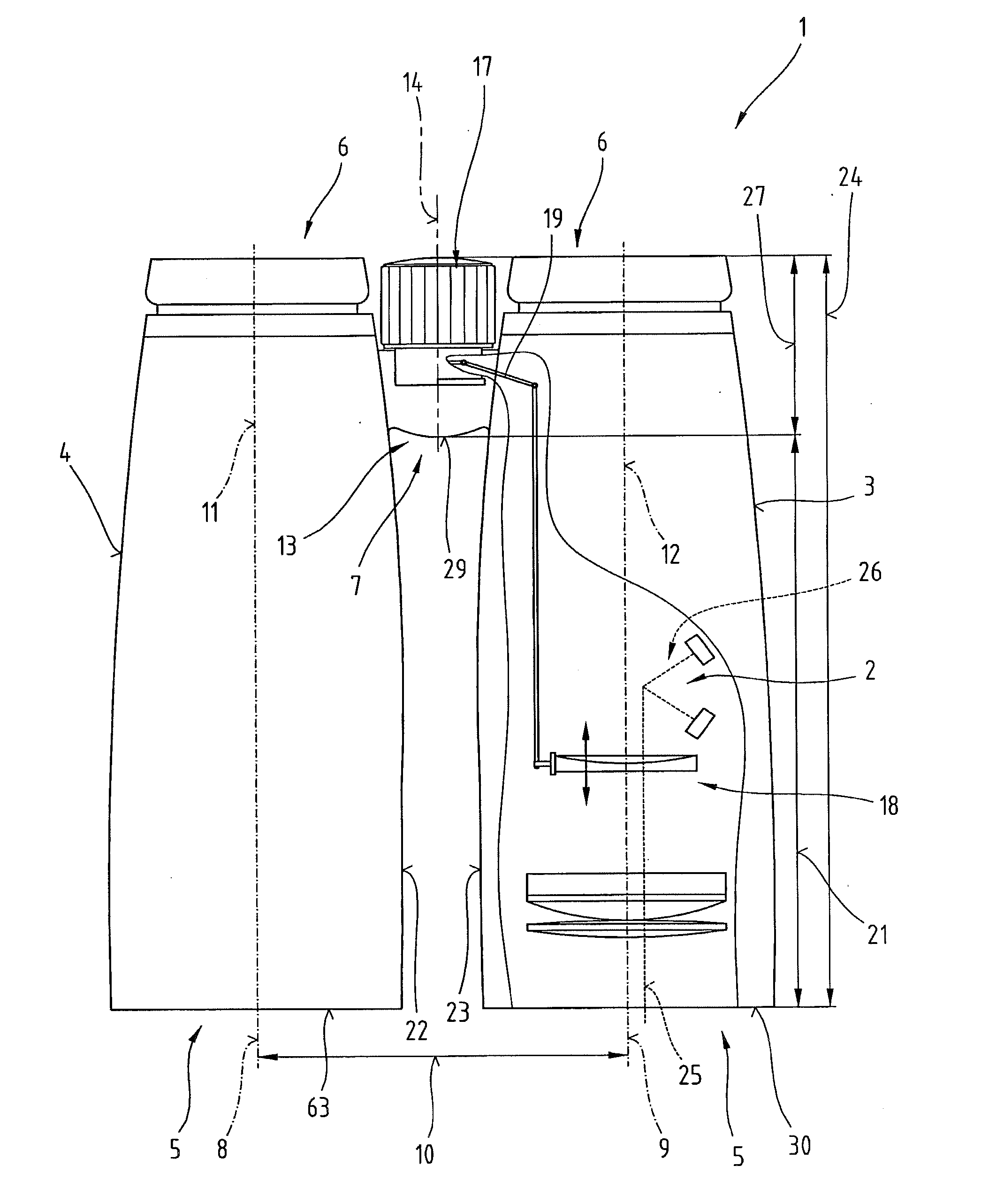
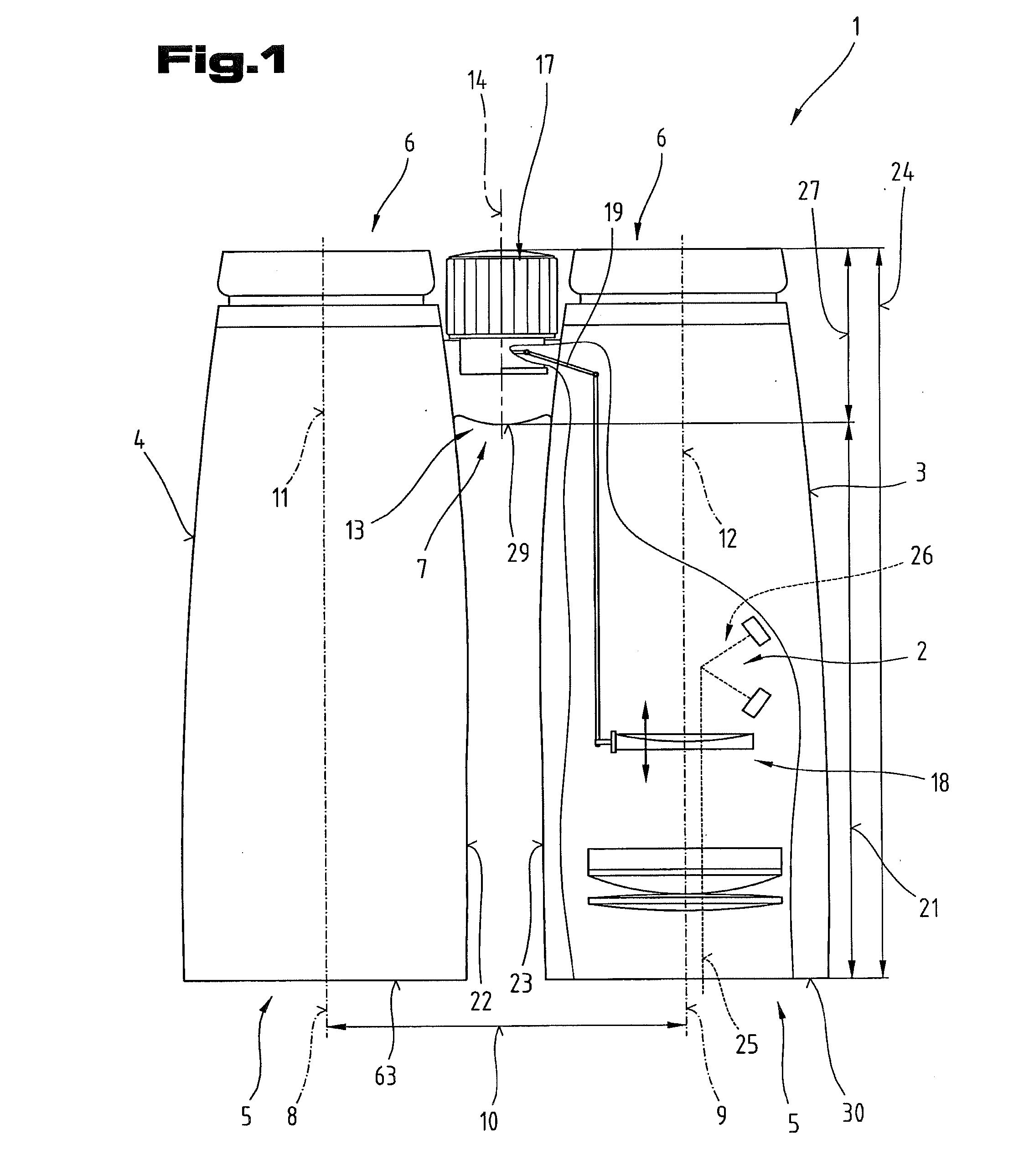
The invention is a long-range optical device that solves the problem of maintaining a balanced weight distribution to accurately sight a target. It includes a range-finding device that allows for automated setting of focus using cheap components with low weight. The device is designed to be easily handled and held in a sighting position for longer periods without fatigue. Additionally, the arrangement of the measurement beam path outside the sub-regions of the observation parts prevents shading or contamination while the device is being held. Overall, this invention improves the approach to the target and facilitates a continuous and accurate sighting.

Problems solved by technology

A disadvantage of these binoculars with a laser range finder is that the handling of the device is made more difficult and none of the desired ergonomics is possible in such binoculars with this corresponding configuration.
A disadvantage of this is that a rotating screen driven by a motor is required, in order to maintain a separation of the emitted laser beam and the reflected laser beam.
Due to the complex structure, a large number of mechanical and optical components are required.
Other long-range optical devices, for example that in DE 197 27 988 A1 and those of DE 69 18 690 U, DE 295 18 708 U1, DE 101 22 936 A1 and DE 27 14 412 A1 also described a very wide range of configurations of laser range finders in connection with visual beam paths, wherein an exact measurement result cannot be achieved however, due to the complex structure and the guiding of the beam.

Method used


Image

  • Observation device with range finder
  • Observation device with range finder
  • Observation device with range finder

Examples


Embodiment Construction

[0045]It should first of all be noted that in the various embodiments described, equivalent parts are assigned identical labels or component designations respectively, the disclosures contained in the entire description being analogously transferrable to equivalent parts with identical labels or component designations. Also, the positional details chosen in the description, such as above, below, to the side etc., refer to the immediately described and illustrated Figure, and when there is a change of position are to be carried over analogously to the new position. Further, individual features or feature combinations from the various exemplary embodiments shown and described can also represent, per se, solutions that are independent, inventive or according to the invention.

[0046]All information on value ranges in the description of the subject matter are to be understood in the sense that they also comprise any and all sub-ranges thereof, e.g. the range 1 to 10 is to be understood to...


PUM


Abstract

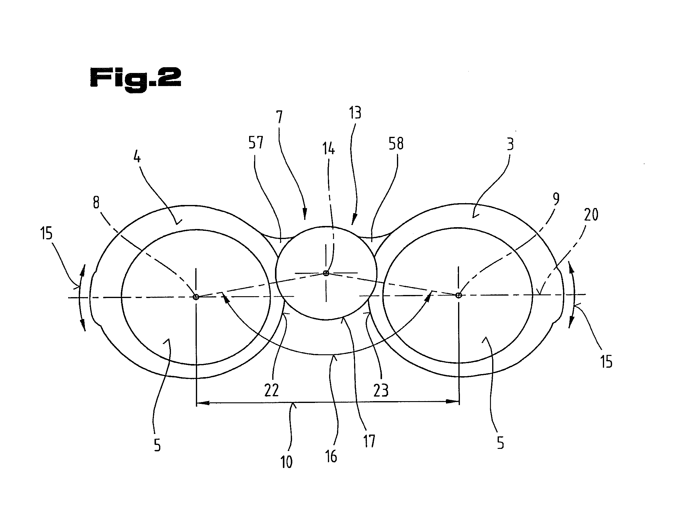
The invention describes a long-range optical device with two observation parts and a first observation beam path and a measurement beam path, in which the two observation parts are arranged essentially parallel next to each other and spaced a predefinable distance apart via at least one connection element. In a plan view of the device 1 with respect to a plane, in which the longitudinal axes of the observation parts are arranged, the sub-regions of the observation parts facing each other lie directly opposite each other over a length aligned parallel to the longitudinal axis of the observation parts of 20% to 90%, preferably 30% to 80% of a length of the observation parts. In addition, the observation beam path and the measurement beam path are arranged outside the sub-regions of the observation parts.

Description

CROSS REFERENCE TO RELATED APPLICATIONS[0001]The present application is a continuation of U.S. patent application Ser. No. 13 / 865,722, filed Apr. 18, 2013, which is a continuation, of U.S. patent application Ser. No. 12 / 865,481, filed on Jul. 30, 2010, which application is a national phase entry under 35 U.S.C. §371 of International Application No. PCT / AT2009 / 000038, filed Jan. 30, 2009, published in German, which claims the benefit of Austrian Patent Application No. A 153 / 2008, filed Jan. 31, 2008; Austrian Patent Application No. A 163 / 2008, filed Feb. 1, 2008; European Patent Application No. 08001979.7, filed Feb. 2, 2008; and U.S. Provisional Application No. 61 / 137,406, filed Jul. 30, 2008. The disclosures of said applications are incorporated by reference herein.BACKGROUND OF THE INVENTION[0002]The invention relates to a long-range optical device having at least two tubes corresponding to the features in the preambles of claims 1 to 4.[0003]Binocular field glasses with a laser r...

Claims


Application Information

Patent Timeline
IPC IPC(8): G01C3/04G01S17/10G01S17/86H04W4/80
CPCB25G1/00B25G1/102F41G3/06G01S7/4812G01S7/4817G01S17/08G01S17/10G02B7/06G02B7/12G02B23/04G02B23/10H04W4/80G01C3/04G02B23/18G01S17/86F41G1/38
Inventor PERNSTICH, LUDWIGROIDER, KONRAD A.ZIMMERMANN, ANDREASLANCASTER, GAVIN
Owner SWAROVSKI-OPTIK AG & CO KG
Learn More