
Surgical glove

a glove and surgical technology, applied in the field of surgical gloves, can solve the problems of hand fatigue, a major issue for surgeons, shape does not address or adequately address the problem of finger stress, etc., and achieve the effects of reducing glove tension, reducing hand fatigue, and improving sensitivity and dexterity

Inactive Publication Date: 2014-06-05
GUAN LOW CHIN
View PDF2 Cites 13 Cited by
  • Summary
  • Abstract
  • Description
  • Claims
  • Application Information

AI Technical Summary

Benefits of technology

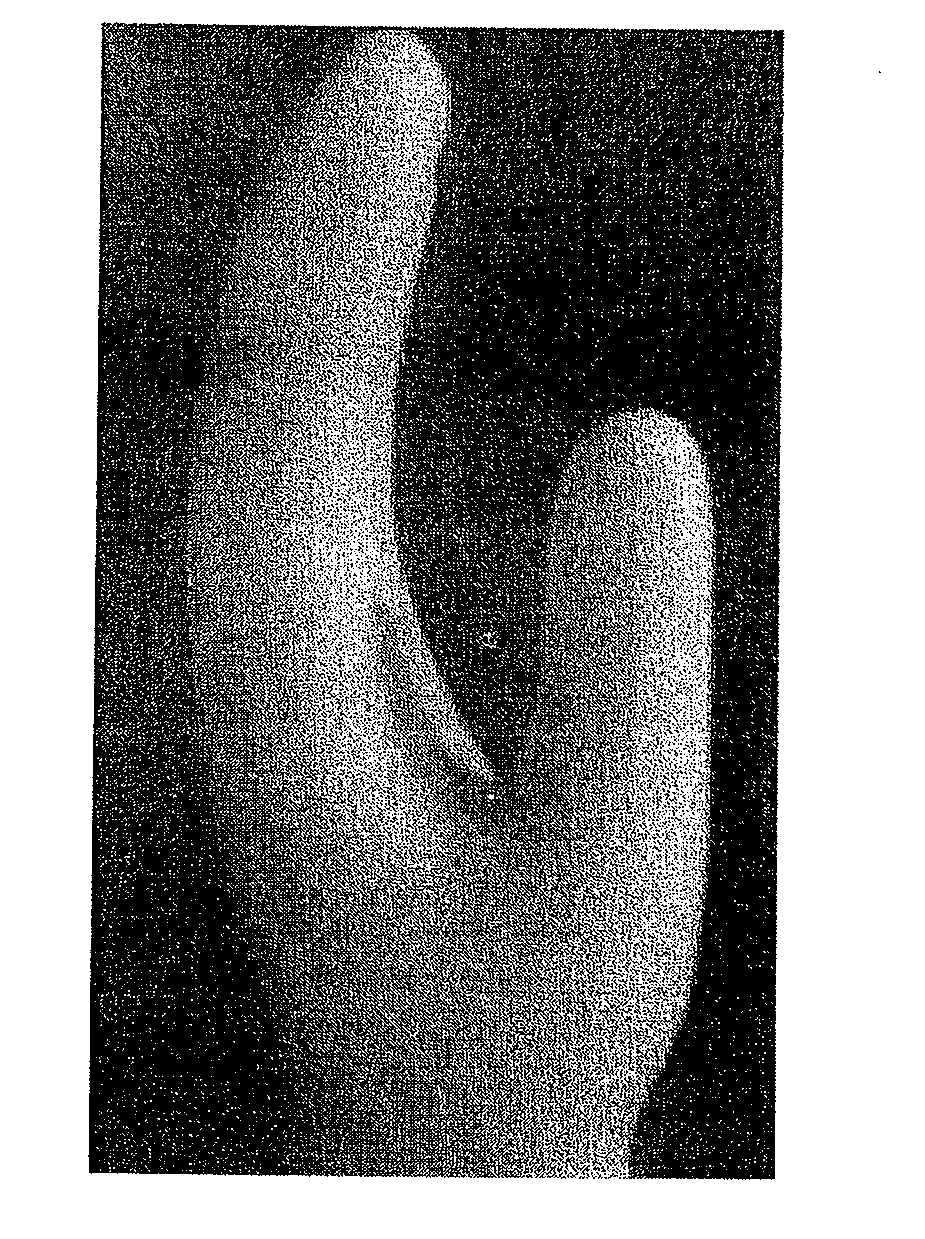
The present invention introduces bends in the fingers of a glove to reduce hand fatigue. By using a mold that creates stress and slack in the glove, it matches the natural position of the surgeon's hands while manipulating a surgical implement. This reduces tension in the glove and improves sensitivity and dexterity while maintaining tightness. Unlike previous technology, the present invention is based on the concept of specific articulation required during surgery.

Problems solved by technology

Nevertheless the amount of time when the gloves are worn on the hands is long enough to cause hand fatigue.
Hand fatigue is a major issue for surgeons due to the protracted length of some of these procedures.
However these shapes do not address or adequately address the problem of finger stress and the related hand fatigue.
There is thus an unfulfilled need for a surgical glove that is able to address the hand fatigue problems faced by those who wear the surgical glove for a long period of time while working with surgical implements.

Method used


Image

  • Surgical glove
  • Surgical glove
  • Surgical glove

Examples


first embodiment

[0049]the invention resides in a mould that has one major bend (Bend 1) in the digits as illustrated in FIG. 6 at the point X. This is to copy the one major bend (Bend 1) of the proximal-middle joint for the index, middle, ring and little fingers. For the thumb, the one major bend (Bend 1) occurs at the metacarpal-proximal joint.

[0050]In order to be suitable for any design of finger lengths, regardless of size, the percentages / ratios and angles rather than absolute dimensions are specified in Table 1. FIG. 6 illustrates how the parameters in Table 1 of the first bend in the form of location of Bend 1 (X) and angle of bend (a) are measured. The range of locations of Bend 1 (X) in percentage (%) for the different parts of the fingers as tabulated in Table 1 are based on general demographic anatomical sizes.

[0051]The angle of bend (a) of the first bend for the index, middle, ring and little fingers is defined as the acute angle formed by the intersection of a first line formed along th...

second embodiment

[0053]the invention resides in a mould that has two major bends in the digits as illustrated in FIG. 7. This is to copy the two bends of the proximal-middle joint and middle-distal bone joint for the index, middle, ring and little fingers. For the thumb, the first bend (Bend 1) occurs at the metacarpal-proximal joint and the second bend (Bend 2) occurs at the proximal-distal joint.

[0054]In this second embodiment, the aggregate of the two bends from the metacarpal line will be the defining angle as measured as angle of bend (c). See Table 2. FIG. 7 illustrates how the parameters as tabulated in Table 2 of the two bends in the form of location of Bend 1 represented by point X and angle of bend (a) and location of Bend 2 represented by point Y and angle of bend (b) are measured. The measurement of the angle of the aggregate angle of bend (c) is also shown. The range of locations of Bend 1 (X) and Bend 2 in percentage (%) for the different parts of the fingers as tabulated in Table 2 ar...


PUM

PropertyMeasurementUnit
included angleaaaaaaaaaa
sizeaaaaaaaaaa
total lengthaaaaaaaaaa

Abstract

A surgical glove is made using a mould having a set of digits, consisting of thumb and index, middle, ring and little fingers that are disposed in positions consistent with that of a human hand when holding a surgical implement. In one embodiment, the digits include at least one major bend. In another embodiment, each of the digits includes two bends. By adopting a shape for the surgical glove that mimics the position of the surgeon's hand while holding a surgical implement, finger stress and hand fatigue during a prolonged surgical procedure can be significantly reduced.

Description

FIELD OF INVENTION[0001]The invention relates generally to a surgical glove and to a hand mould for making such a glove. More specifically, the invention concerns a surgical glove which may be worn by a surgical doctor for an extended period of time while performing surgery.BACKGROUND OF THE INVENTION[0002]In the course of a surgical procedure, a typical surgical glove is worn while the doctor is performing a surgery in a surgery room. A typical surgical glove can be worn from as little as 10 minutes to more than 15 hours to complete a procedure. In the course of a long surgery, many pairs of gloves are changed for cleanliness, leaving the surgical room for rest or food, good sterile practice, etc. Nevertheless the amount of time when the gloves are worn on the hands is long enough to cause hand fatigue. Such length of time puts a physical stress on the hands of the surgeon as the gloves are designed to be worn tight without slack or loose folds in order to maximize dexterity and se...

Claims


Application Information

Patent Timeline
Patent Type & Authority Applications(United States)
IPC IPC(8): A41D19/015
CPCA41D19/01582B29C41/14A41D19/04A41D19/0062B29C41/40A61B42/00F04C2270/0421
Inventor GUAN, LOW CHIN
Owner GUAN LOW CHIN
Learn More