Polarized lens

a polarized lens and lens technology, applied in the field of polarized lenses, can solve the problems of the prior art polarized lens having problems, and achieve the effects of small specific gravity, reduced thickness, and reduced weigh

Active Publication Date: 2014-05-29
SHUYU
View PDF2 Cites 7 Cited by
  • Summary
  • Abstract
  • Description
  • Claims
  • Application Information

AI Technical Summary

Benefits of technology

[0015]The polarized lens of the invention has a laminated structure in which the polarized film is sandwiched by the glass lens and the resin lens and the resin lens has a smaller specific gravity than the glass lens and the thickness thereof is reduced. Therefore, the weight is very much reduced in comparison with the laminated polarized lens of the prior art formed by sandwiching a polarized film between the front side glass lens and the back side glass lens.
[0016]Further, the thickness of the polarized lens is very much reduced, and hence the polarized lens of the invention matches a case of being fitted to lightweight and slim frames without any change from a general lens. In other words, a heavy and thick polarized lens as in the prior art cannot match with lens frames of recent years formed of a thin wire rod. However, the polarized lens of the invention may be employed for any frames owing to its lightweight and thin profile.
[0017]Furthermore, when fitting the polarized lens to the rim, distortion caused by a stress or the like is generated. Such a distortion may be caused by an internal stress remaining in the lens when the lens is molded as a matter of course. However, such a distortion occurs often when the shapes of the lens and the rim do not match or when the lens curve and the curve of groove of the frame do not match. In the invention, the distortion occurring when the polarized lens is mounted into the rim is suppressed by increasing stiffness of the polarized lens with use of a glass lens on one side, and the remaining stress at the time of molding is suppressed as much as possible by employing the resin lens having a thin profile on the other side.

Problems solved by technology

As seen above, the polarized lens of the prior art have the problems as described above.

Method used


Image

  • Polarized lens
  • Polarized lens
  • Polarized lens

Examples


Embodiment Construction

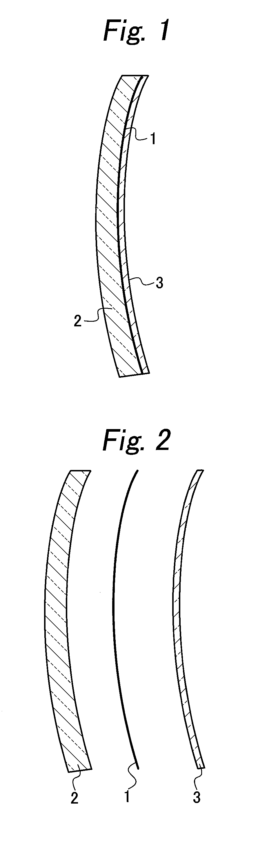
[0021]FIG. 1 and FIG. 2 illustrate a cross section of a polarized lens according to an embodiment of the invention. In these drawings, reference numeral 1 denotes a polarized film, reference numeral 2 denotes a glass lens and reference numeral 3 denotes a resin lens. The polarized lens illustrated in these drawings has a laminated structure in which the polarized film 1 is sandwiched by the glass lens 2 and the resin lens 3 from both sides, and the glass lens 2 is provided on the front side and the resin lens 3 is provided on the rear side. It is also possible to adopt a laminated structure in which the resin lens is arranged on the front side and the glass lens is arranged on the back side.

[0022]The polarized film 1 is stuck on the back side of the glass lens 2 and the resin lens 3 is stuck on the back side of the polarized film 1. Here, the resin lens 3 may be formed by dropping fused resin on the polarized film 1 and bringing a mold which does not adhere to the resin into tight c...


PUM


Abstract

A thin and lightweight polarized lens is disclosed. The polarized lens has a laminated structure having a polarized film provided in a sandwiched manner, a glass lens is provided on a front side and a resin lens is provided on a back side, and the resin lens on the back side has a thickness of a range from 0.05 mm to 0.50 mm.

Description

BACKGROUND OF THE INVENTION[0001]1. Field of the Invention[0002]The present invention relates to a polarized lens reduced in weight and thickness for making glasses convenient to wear.[0003]2. Prior Art[0004]Sunlight is a mixed wave of a longitudinal wave and a transversal wave, and a polarized lens having an optical anisotropic aspect is configured to select one of oscillating waves from the longitudinal wave and the transversal wave and allow the selected wave to pass through and block the other wave from passing therethrough when the sunlight passes through the polarized lens. Therefore, the polarized lens prevents glaring of water surfaces, road surfaces, or roof tiles due to reflected sunlight, protects wearer's eyes from blinding light, and is an optimum lens for the strong sun in summer. If only shielding the sunlight is wanted, sunglasses will do. However, the sunglasses do not have a function to block one of the oscillating waves of the sunlight, and hence cannot prevent th...

Claims


Application Information

Patent Timeline
Patent Type & Authority Applications(United States)
IPC IPC(8): G02B27/28
CPCG02B27/28G02C7/12G02C2202/16
Inventor SAKAI, YUICHI
Owner SHUYU
Why Eureka
Try Eureka