
Camless engine operating system

a technology of operating system and cam, which is applied in the direction of valve arrangement, machines/engines, non-mechanical valves, etc., can solve the problems of cam and rocker arm wear and tear, damage to both the piston and the valve, and other parts

Inactive Publication Date: 2014-05-29
KELI JACOB B +1
View PDF6 Cites 2 Cited by
  • Summary
  • Abstract
  • Description
  • Claims
  • Application Information

AI Technical Summary

Benefits of technology

The present invention is about a system for operating a camless engine using an electronic mechanism to control the movement of pistons. This system includes an electronic actuating mechanism and a coordination assembly to manage the actuation. The technical effect of this invention is to provide a more efficient and precise way of controlling the movement of pistons in a camless engine, which can improve performance and reliability.

Problems solved by technology

At a very high speed, these springs have to be very strong, otherwise the valves might lose contact with the rocker arm.
This can result in extra wear and tear on the cams and rocker arms.
These chains and belts need to be changed regularly as per the engine's maintenance schedule, because if they break, the camshaft stops spinning and the piston will hit the open valve and damage both the piston and the valve as well as other parts.
The long rods add mass to the system, which increases the load on the valve springs.
In the typical internal combustion engine, the use of camshafts results in a power loss of the engine of 20%.

Method used


Image

  • Camless engine operating system
  • Camless engine operating system
  • Camless engine operating system

Examples


Embodiment Construction

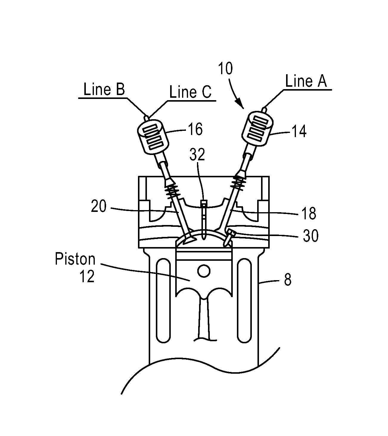
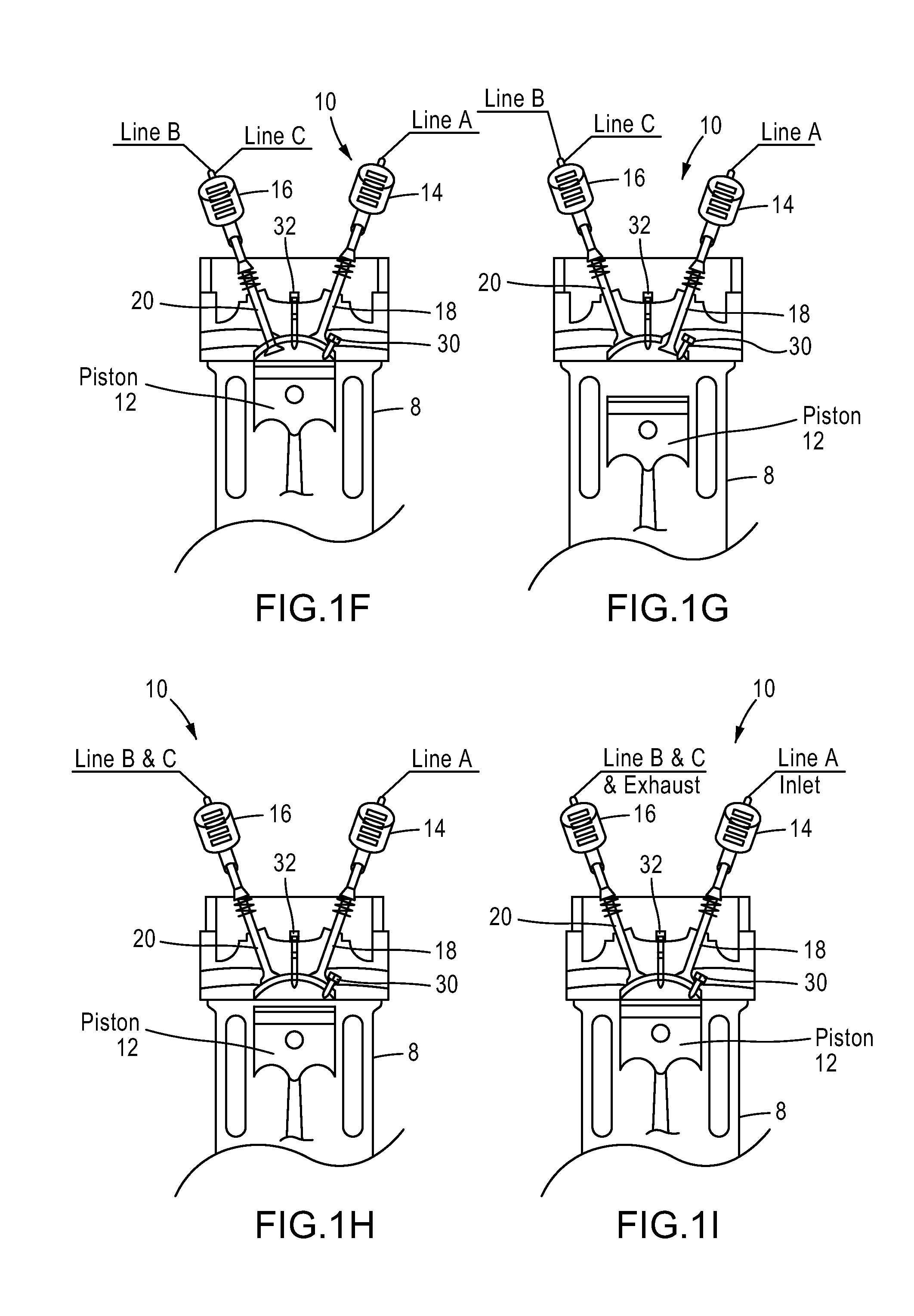
[0030]The present invention is generally directed to a camless engine operating system and methods for actuating pistons and valves electronically in any vehicle or device that uses an engine. The camless engine operating system 2 of the present invention can increase the efficiency of the engine over traditional engines by at least 20%. Essentially, the present invention changes the prior mechanical control of the engine to an electronic control. The camless engine operating system 2 allows an engine to be operated without camshafts as compared to standard prior art engines that require a camshaft.

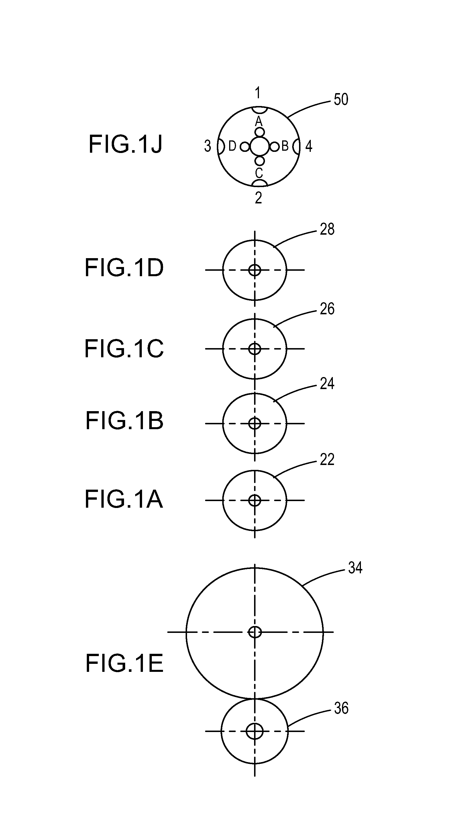
[0031]In the preferred embodiment, the camless engine operating system 2 includes least one electronic actuation mechanism 10. As shown in FIGS. 1A and 1B, the electronic actuation mechanism 10 operates at least one inlet valve 18 or at least one exhaust valve 20, and preferably both at least one intake valve 18 and at least one exhaust valve 20. Preferably, the electronic actuation mecha...


PUM


Abstract

A camless engine operating system that includes an inlet valve switch configured to detect rotational movement of an inlet valve power disc and to output an inlet actuator voltage. A voltage level of the inlet actuator voltage is synchronous with the rotational movement of the inlet valve power disc. An inlet valve is movable to open and close an intake port of a combustion chamber. An inlet valve mechanical force moves the inlet valve to open the intake port. An inlet actuator is configured to exert the inlet valve mechanical force onto the inlet valve. The inlet actuator voltage received by the inlet actuator controls the inlet actuator to exert the inlet valve mechanical force onto the inlet valve.

Description

CROSS REFERENCES TO RELATED APPLICATIONS[0001]The present invention claims priority from U.S. Provisional Application No. 61 / 730,098, filed on Nov. 27, 2012, the entire contents of which being incorporated herein by reference.BACKGROUND OF THE INVENTION[0002]1. Technical Field[0003]The present invention relates to engines. More specifically, the present invention relates to camless engines and to methods of improving efficiency of engines.[0004]2. BACKGROUND ART[0005]Internal combustion engines that utilize pistons have been used in automobiles and other motorized devices for many years. Conventional camshafts are used to control the opening of the valves and are driven by a crankshaft. The camshaft is designed to rotate either in the engine block or on the cylinder head to open and close the valves. The camshaft is driven by the crankshaft and the camshaft includes egg-shaped surfaces called cam-lobes to open the valves. The position of the lobe is precise in opening and closing th...

Claims


Application Information

Patent Timeline
Patent Type & Authority Applications(United States)
IPC IPC(8): F01L9/04F01L9/20F01L9/26
CPCF01L9/04F01L9/26F01L9/20
Inventor VUAI, ABBAS M.KELI, JACOB B.
Owner KELI JACOB B
Learn More