
Wireless power receiver for increased charging efficiency

a technology of power receiver and wired receiver, which is applied in the direction of safety/protection circuit, transportation and packaging, sustainable buildings, etc., can solve the problems of reducing the overall charging efficiency of two independent units, the problem of an increase in the mounting area, and the inability to charge the battery correctly

Inactive Publication Date: 2014-05-22
SAMSUNG ELECTRONICS CO LTD
View PDF3 Cites 273 Cited by
  • Summary
  • Abstract
  • Description
  • Claims
  • Application Information

AI Technical Summary

Benefits of technology

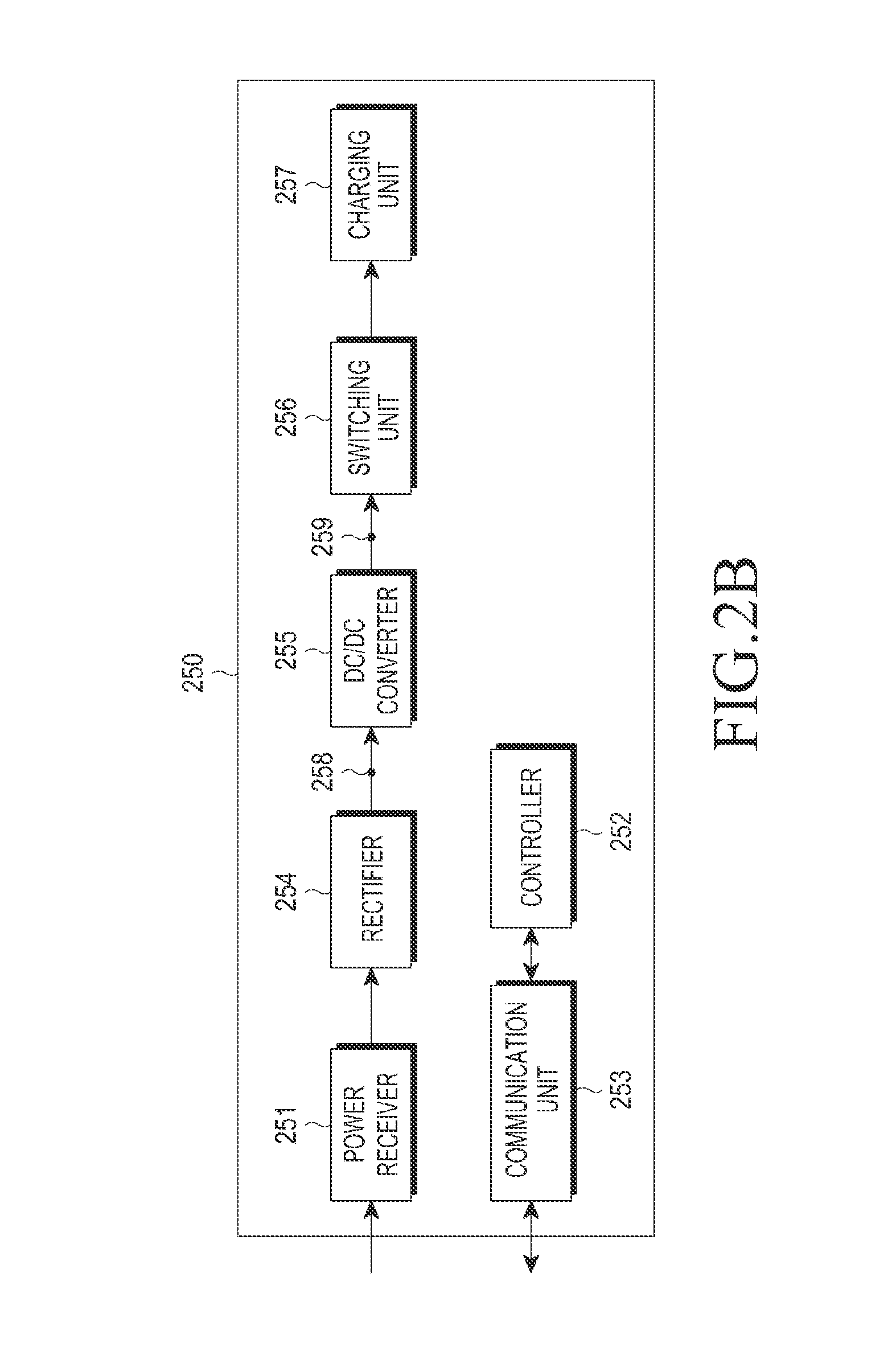
The present invention provides a wireless power receiver with a power processing IC that can charge and perform DC / DC conversion at the same time. This allows for more efficient use of the charging power and reduces the need for additional components. The power processing IC can convert the voltage of the charging power into the specific voltage needed for the wireless power receiver to operate. This results in improved performance and reliability of the wireless power receiver.

Problems solved by technology

However, in such a contact-type charging scheme, the contact terminals protrude outwardly and become easily contaminated by foreign substances and moisture, causing incorrect battery charging.
Specifically, the wireless power receiver according to the related art independently includes the charger and the DC / DC converter, and thus has a problem of an increase in mounting area.
Moreover, the wireless power receiver according to the related art has a problem in that the two independent units may reduce overall charging efficiency.

Method used


Image

  • Wireless power receiver for increased charging efficiency
  • Wireless power receiver for increased charging efficiency
  • Wireless power receiver for increased charging efficiency

Examples


Embodiment Construction

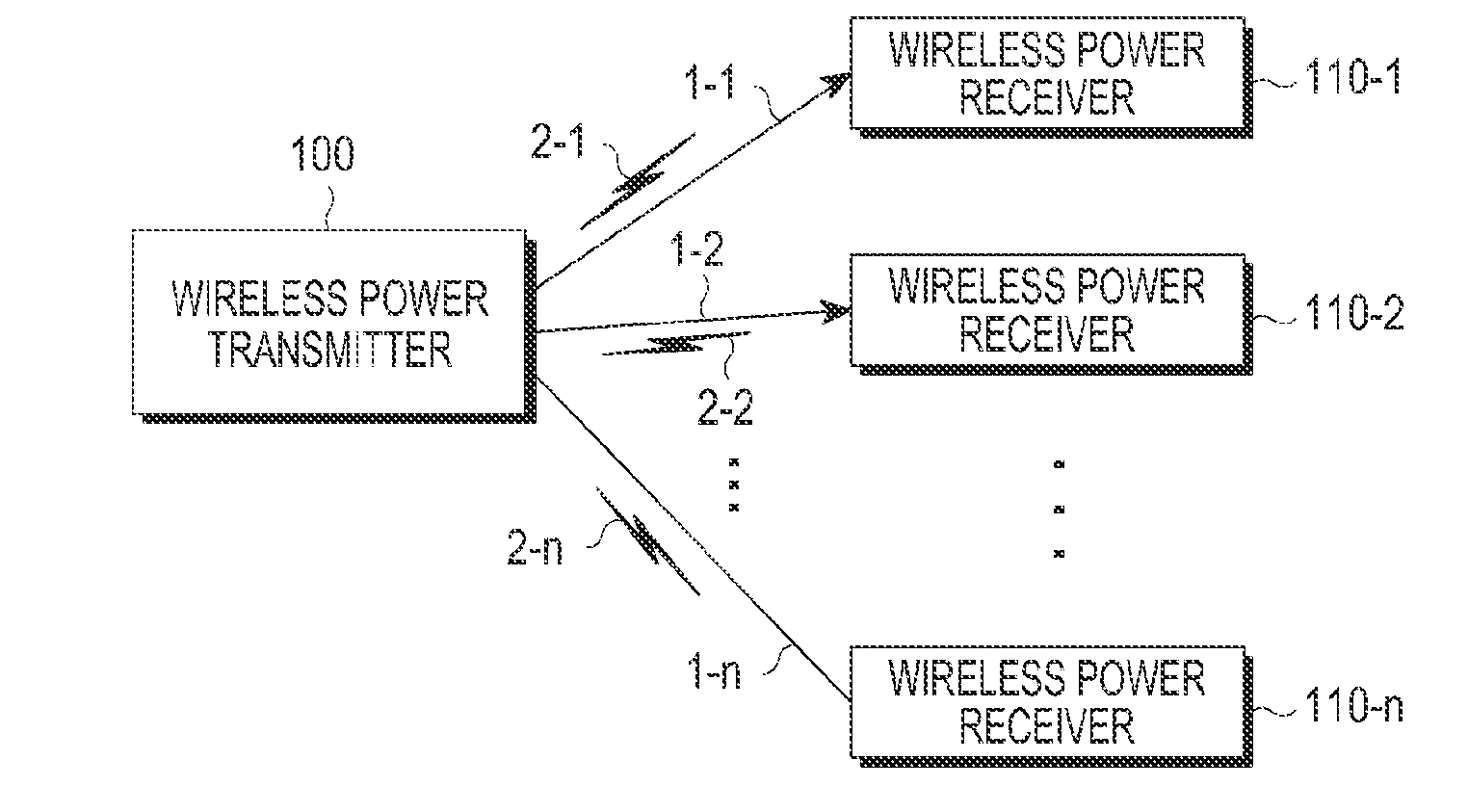
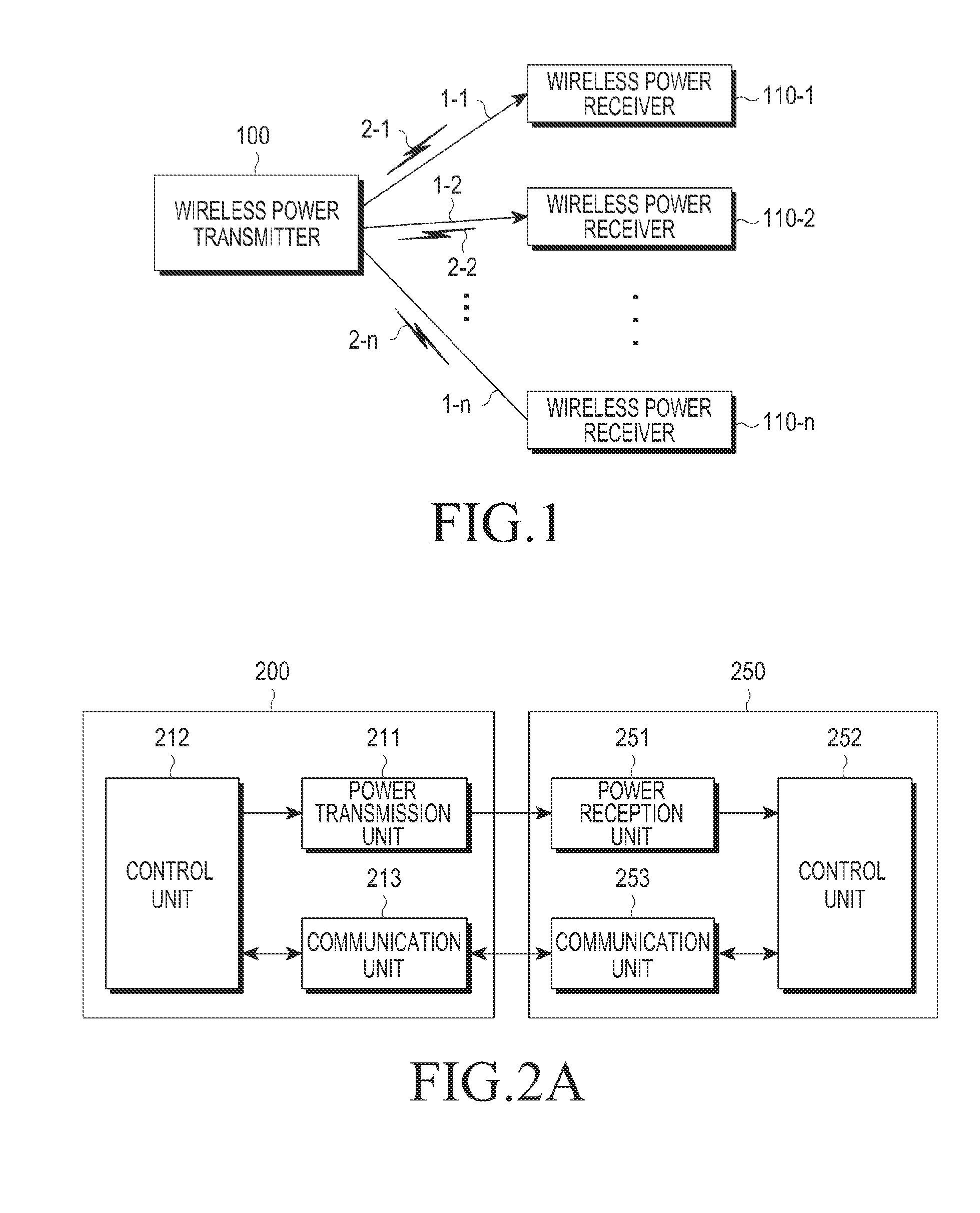
[0028]The following description with reference to the accompanying drawings is provided to assist in a comprehensive understanding of embodiments of the invention as defined by the claims and their equivalents. It includes various specific details to assist in that understanding but these are to be regarded as examples. Accordingly, those of ordinary skill in the art will recognize that various changes and modifications of the embodiments described herein can be made without departing from the scope and spirit of the invention. In addition, descriptions of well-known functions and constructions may be omitted for the sake of clarity and conciseness.

[0029]The terms and words used in the following description and claims are not limited to their dictionary meanings, but, are merely used to enable a clear and consistent understanding of the invention. Accordingly, it should be apparent to those skilled in the art that the following description of embodiments of the present invention is ...


PUM


Abstract

A wireless power receiver for receiving charging power from a wireless power transmitter includes a power reception unit configured to receive the charging power, a rectification unit configured to rectify charging power provided by the power reception unit, and output charging power in a form of Direct Current (DC), a charging unit configured to store charging power, and a power processing Integrated Chip (IC) configured to convert a voltage of the output rectified charging power, into at least one voltage, that an operation of the wireless power receiver requires, and output power having the at least one voltage. Accordingly, charging efficiency is increased.

Description

PRIORITY[0001]This application claims priority under 35 U.S.C. §119(a) to a Korean patent application filed on Nov. 20, 2012 in the Korean Intellectual Property Office and assigned Serial No. 10-2012-0131534, the contents of which are incorporated herein by reference.BACKGROUND OF THE INVENTION[0002]1. Field of the Invention[0003]The present invention relates generally to a wireless power receiver, and more particularly, to a wireless power receiver for increased charging efficiency.[0004]2. Description of the Related Art[0005]Mobile terminals such as mobile phones and Personal Digital Assistants (PDAs) are powered by rechargeable batteries that are charged with electrical energy by a separate charging device. Typically, a separate contact terminal is formed at the outer side of each of the charging device and the battery, which are electrically connected to each other through a contact between the two separate contact terminals.[0006]However, in such a contact-type charging scheme,...

Claims


Application Information

Patent Timeline
Patent Type & Authority Applications(United States)
IPC IPC(8): H02J7/02
CPCH02J7/025H02J7/00034H02J50/80H02J50/12H02J50/40H02J50/005H02J7/00302H02J7/00304Y02B40/00
Inventor KIM, YU-SUBYUN, KANG-HO
Owner SAMSUNG ELECTRONICS CO LTD
Learn More