
Vacuum electric cooker

a technology of electric cooker and vacuum chamber, which is applied in the direction of cooking vessels, cooking plants, and vessels with intergral heating, can solve the problems of nourishing components and container breakage, and achieve the effects of reducing weight, simplifying structure and convenient use for users

Active Publication Date: 2014-05-22
TESCOM CORP
View PDF5 Cites 28 Cited by
  • Summary
  • Abstract
  • Description
  • Claims
  • Application Information

AI Technical Summary

Benefits of technology

The vacuum electric cooker in this patent has a simplified structure and reduced weight compared to traditional vacuum pumps. The vacuum pump is located in the cooker body, instead of the cover, which makes it easier for users to use and reduces stress on the container. The cooker also includes a trap member with an air-flow buffering tube to prevent material for cooking or liquid from entering the vacuum pump. The control means activates the vacuum pump first at the start of the cooker to evacuate the container and maintain a predetermined vacuum degree. The pressure detecting means sends a vacuum drop signal when the vacuum degree drops, and the control means activates the vacuum pump to raise the vacuum degree back to the predetermined level. This ensures that the material for cooking is kept fresh and the cooking process is efficient.

Problems solved by technology

Even if a fresh juice is made by the aforementioned mixer of the conventional structure, however, the juice has its food components progressed in decomposition and oxidation as the time elapses, so that the nourishing components do nothing but decrease.
Thus, said cover becomes hard for the works of the worker and causes serious stresses on the container so that it causes a breakage of the container in the worst case.

Method used


Image

  • Vacuum electric cooker
  • Vacuum electric cooker
  • Vacuum electric cooker

Examples


Embodiment Construction

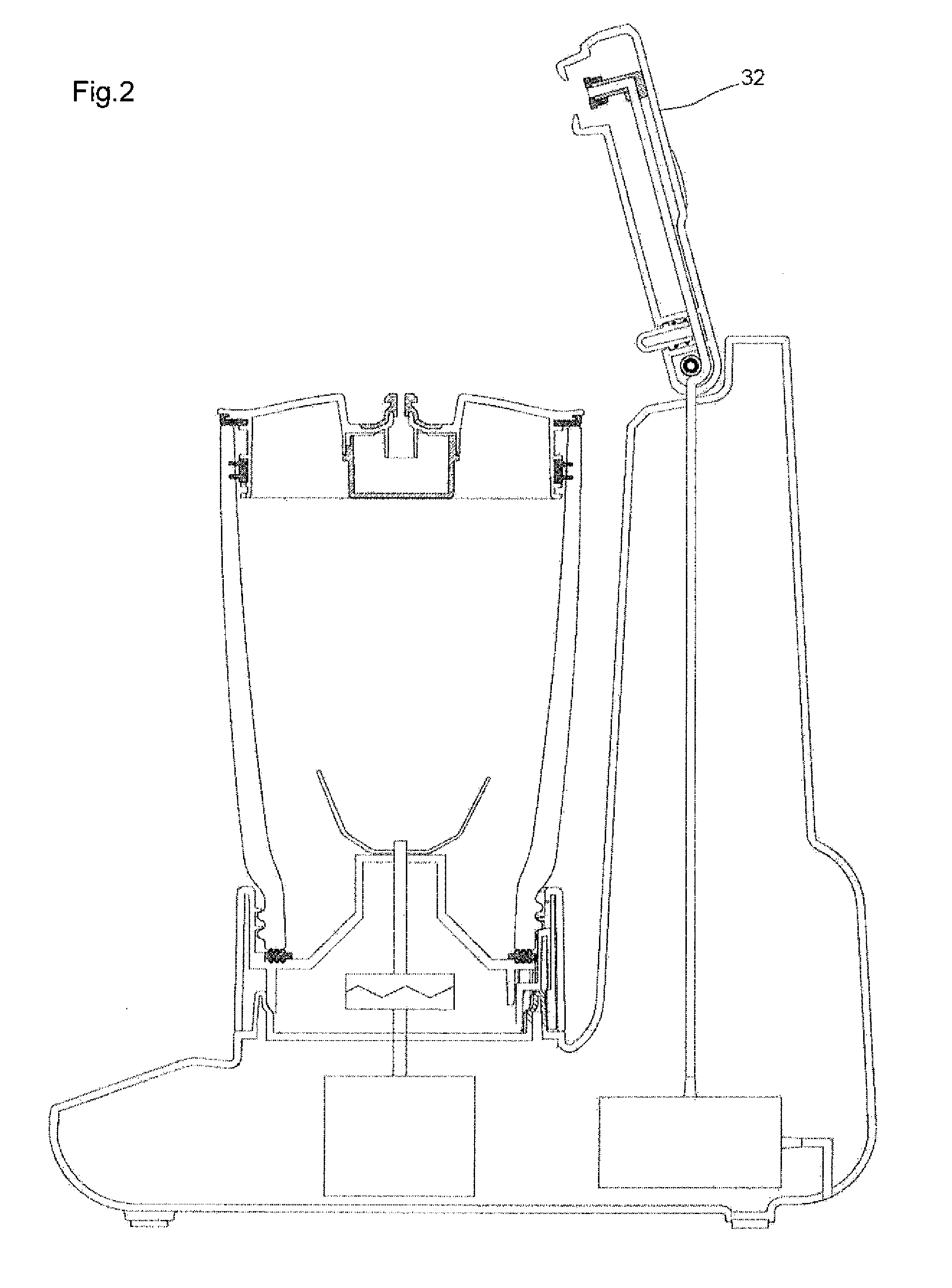
[0056]The vacuum electric cooker according to a mode of embodiment of the present invention will be described in detail with reference to the accompanying drawings.

[0057]A vacuum electric cooker 10 according to the mode of embodiment of the invention is provided with a cooker body 12. This cooker body 12 is equipped with a horizontal base 14 and a stand section 16 extending vertically upward from the rear edge of that horizontal base 14. A motor 18 is built in the horizontal base 14 of the aforementioned cooker body 12.

[0058]The present vacuum electric cooker 10 is provided with a cooker container 20. This cooker container 20 is equipped with: a cooker container body 24 having a cooking tool 22 to be driven by the aforementioned motor 18; and a cover member 28 having a discharge nozzle 26 for covering the aforementioned cooker container body 24. The horizontal base 14 of the aforementioned cooker body 12 is equipped with an annular container base 30 for fitting and fixing the lower ...


PUM


Abstract

The present invention has an object to provide a vacuum electric cooker as can be easily worked by an operator and as can minimize a stress to be applied to the container.A vacuum electric cooker of this invention comprises a cooker body including a horizontal base and a stand section, a cooker container including a cooking tool, a cover member having a discharge nozzle, a connecting arm having a base end attached to said stand section as to rock in a vertical plane between a horizontal active position and a vertical inactive position, a connecting nozzle attached to said connecting arm and connected to said discharge nozzle when said connecting arm is at the active position, a vacuum pump disposed in said cooker body, and a tube connected to said vacuum pump and said connecting nozzle.

Description

CROSS-REFERENCE TO RELATED APPLICATION[0001]This application is based upon and claims benefit of priority from the Japanese Patent Application No. 2012-222634 filed on Oct. 5, 2012, which is incorporated herein by reference in its entirety.TECHNICAL FIELD[0002]The present invention relates to a vacuum electric cooker and, more particularly, to a vacuum electric cooker for cutting, pulverizing and agitating a food material while the inside of a container is being evacuated.BACKGROUND ART[0003]While an inclination to a healthy life for foods is being intensified in recent years, an interest is being raised in the vegetable juices or soups, through which many vegetables can be easily eaten. Another interest is also heightened to an electric cooker such as the juicer or mixer, by which those vegetable juices or soups can be home-made.[0004]In the prior art, the electric cooker having the functions to cut, crush and agitate the foods (or food materials) is well known as the mixer (as ref...

Claims


Application Information

Patent Timeline
Patent Type & Authority Applications(United States)
IPC IPC(8): A47J27/00
CPCA47J27/004A47J27/002A47J27/04A47J43/046A47J43/0716A47J43/07
Inventor ARAI, RIETOKUSHIGE, MAROTSUKUDA, SACHIOKAKUTA, KENJIMARUYAMA, FUMIYASU
Owner TESCOM CORP
Learn More