
Dipole Antenna and Radio-Frequency Device

Active Publication Date: 2014-05-15
WISTRON NEWEB
View PDF4 Cites 35 Cited by
  • Summary
  • Abstract
  • Description
  • Claims
  • Application Information

AI Technical Summary

Benefits of technology

The invention provides a dipole antenna and radio-frequency device that improves antenna performance and balances feed-in impedance. This results in better signal quality and more consistent performance.

Problems solved by technology

As a result, the antenna performance of the dipole antenna may be changed once the co-axial cable 14 is changed, e.g. impedance changes by cable routes, which may decrease stability and reliability of the dipole antenna 11 during manufacture.

Method used


Image

  • Dipole Antenna and Radio-Frequency Device
  • Dipole Antenna and Radio-Frequency Device
  • Dipole Antenna and Radio-Frequency Device

Examples


Embodiment Construction

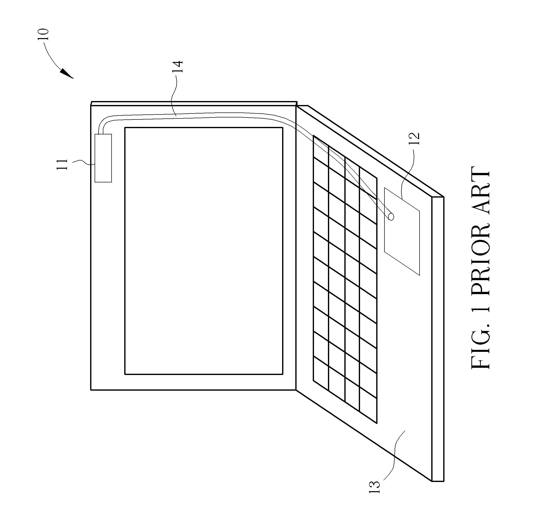
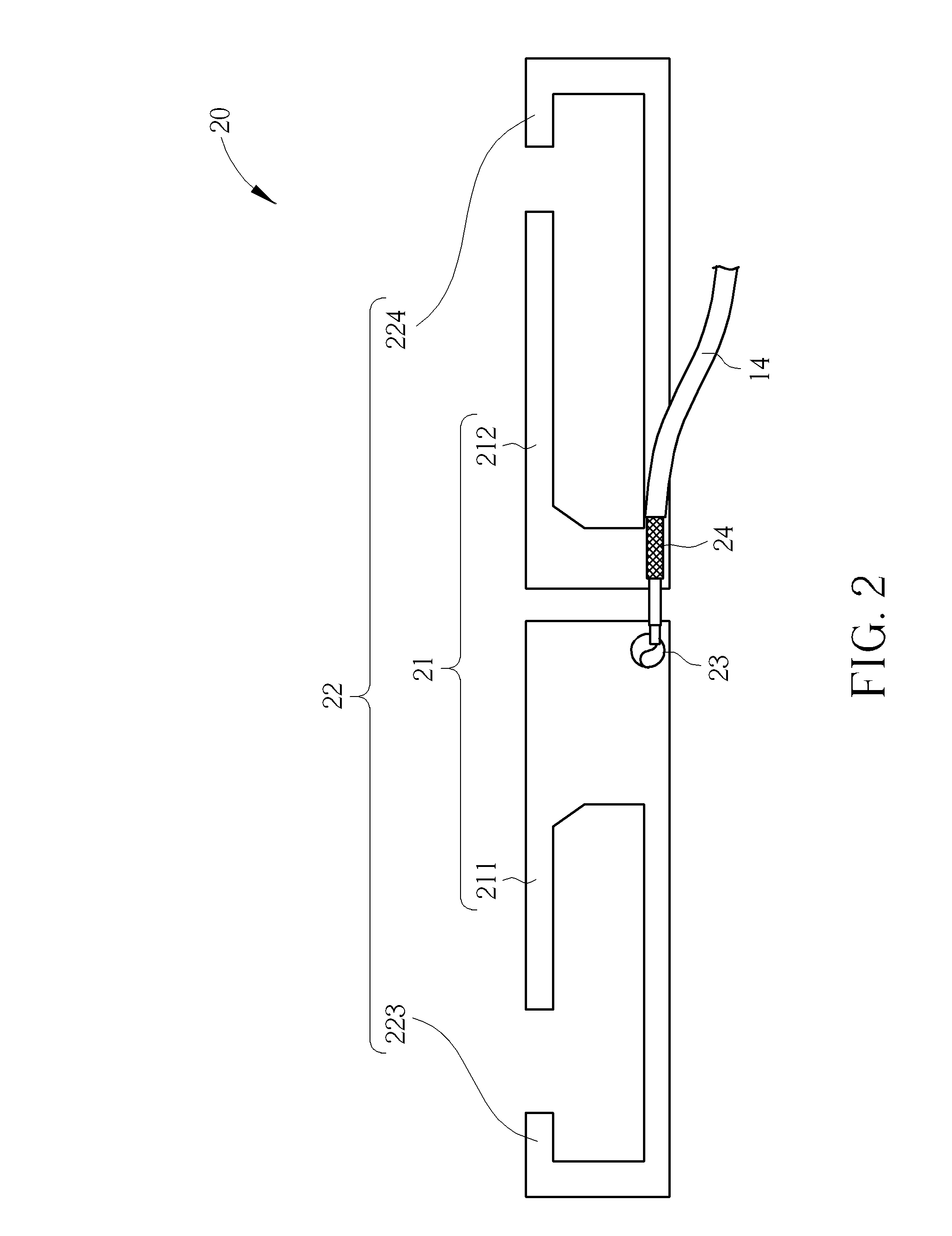
[0020]Please refer to FIG. 2, which is a schematic diagram of a dipole antenna 20. The dipole antenna 20 maybe substituted for the antenna 11 shown in FIG. 1, and used for transmitting and receiving an RF (Radio-Frequency) signal, and the RF signal may be transmitted to the RF signal process unit 12 (not shown in FIG. 2) by the co-axial cable 14. The dipole antenna 20 includes a feed-in terminal 23, a first radiator 21 and a second radiator 22. The feed-in terminal 23 is used for feeding in the RF signal. The first radiator 21 is electrically connected to the feed-in terminal 23 for radiating the RF signal in a high frequency band. The second radiator 22 is electrically connected to the first radiator 21 and the feed-in terminal 23 for radiating the RF signal in a low frequency band.

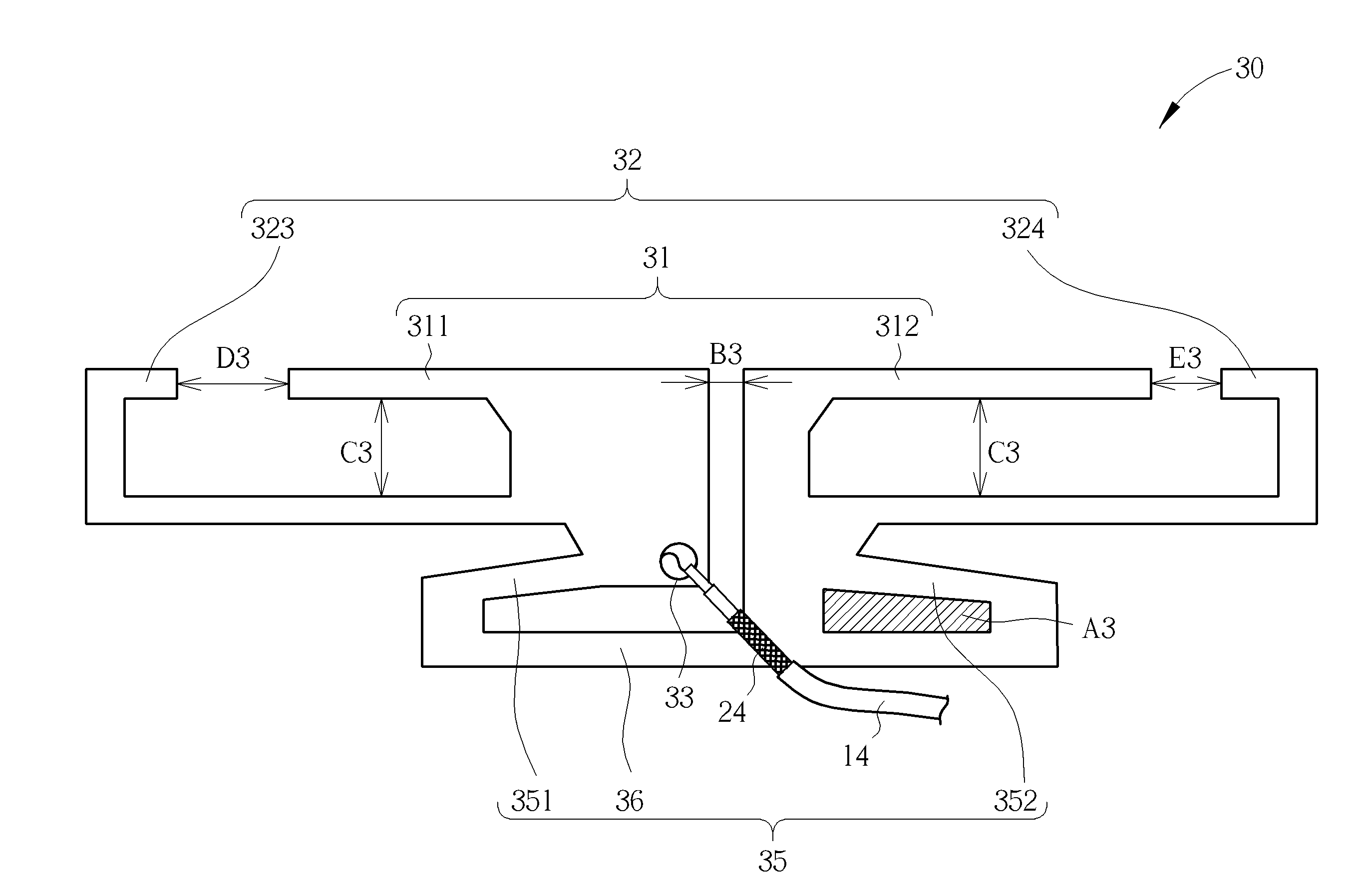
[0021]In detail, the first radiator 21 includes a first arm 211 and a second arm 212, wherein the first arm 211 is electrically connected to the feed-in terminal 23, the second arm 212 is electrically co...


PUM


Abstract

A dipole antenna is disclosed. The dipole antenna includes a feed-in terminal, a balun, a first radiator and a second radiator. The feed-in terminal is used for feeding in a radio-frequency signal. The balun is electrically connected to the feed-in terminal for driving out a return current of the dipole antenna to balance a feed-in impedance of the dipole antenna. The first radiator is electrically connected to the feed-in terminal and the balun for radiating the radio-frequency signal in a first frequency band. The second radiator is electrically connected to the first radiator, the feed-in terminal and the balun for radiating the radio-frequency signal in a second frequency band.

Description

BACKGROUND OF THE INVENTION[0001]1. Field of the Invention[0002]The present invention relates to a dipole antenna and radio-frequency device, and more particularly, to a dipole antenna and radio-frequency device having a balun to balance a feed-in impedance.[0003]2. Description of the Prior Art[0004]An antenna is used for transmitting or receiving radio waves, to communicate or exchange wireless signals. An electronic product with a wireless communication function, such as a tablet computer, a laptop or a personal digital assistant (PDA), usually accesses a wireless network through a built-in antenna.[0005]Please refer to FIG. 1, which is a schematic diagram of an RF (Radio-Frequency) device 10. The RF device 10 has a function of wireless communication; take a note book computer for example. The RF device 10 includes an antenna 11, an RF signal process unit 12 and a housing 13. In general, to prevent the antenna 11 from being disposed within a metallic environment, such as a central...

Claims


Application Information

Patent Timeline
IPC IPC(8): H01Q9/16
CPCH01Q9/16H01Q9/285H01Q5/364H01Q5/371H01Q1/2266
Inventor WANG, CHIH-MINGCHEN, KUAN-CHUNGCHIANG, YU-YU
Owner WISTRON NEWEB
Learn More