
Shovel Attachment

a technology of shoveling and shoveling ring, which is applied in the field of shoveling ring, can solve the problems of time-consuming and exhausting manual shoveling, bodily injuries, and dangerous activities, and achieve the effect of less energy and movemen

Inactive Publication Date: 2014-05-15
STACHOWSKI BREANNA L
View PDF3 Cites 16 Cited by
  • Summary
  • Abstract
  • Description
  • Claims
  • Application Information

AI Technical Summary

Benefits of technology

The patent describes an attachment that can be used as a handle for a snow shovel. It can be tightened around the shovel neck to create friction and allow for easier rotation. The attachment can also connect two shovels together to create a snow plow, making it easier to push with two handles. Overall, the attachment improves the user's comfort and efficiency while using the snow shovel.

Problems solved by technology

Manually removing snow from sidewalks and drive ways is time-consuming and exhausting.
Shoveling can be a dangerous activity, in part because of the strenuous, physical motions required to bend, scoop the snow, lift the load, and then dump the snow.
The repetitive motions and strenuous nature of shoveling may result in bodily injuries, especially to the back; overexertion; and even heart failure.
A standard shovel requires significant bending to scoop the snow, causing the user to practice unsafe positions across a large range of back movements, including a twisting motion in the lower back of a shovel user.
Despite the progress that ergonomic shovels have made in reducing some strain to the back, dumping the snow still required the user to employ awkward body positions, including twisting the torso.
In addition, standard snow shovels are poorly suited to clear larger areas, such as large driveways or parking areas.
Too wide a shovel blade may make it difficult for users to use the shovel based upon the strength required to lift and dump the snow.
And, a wide blade shovel or snow plow is not well suited for clearing tighter areas, including steps and narrow sidewalks.
Maintaining a separate snow plow and snow shovel requires extra space for storing these large tools and of course, additional expense in purchasing both items.

Method used


Image

  • Shovel Attachment
  • Shovel Attachment
  • Shovel Attachment

Examples


Embodiment Construction

[0032]Aspects of the system and methods are described below with reference to illustrative embodiments. The references to illustrative embodiments below are not made to limit the scope of the invention in any way. Instead, illustrative embodiments are used to aid in the description of various aspects of the system and method. The description, made by way of example and reference to illustrations, is not meant to be limiting with regards to any aspect of the invention.

[0033]Devices and methods described in this application are especially well adapted for use in clearing and removing snow and will be described in that context. It will become apparent, however, that this is illustrative of only one utility of the described apparatuses and methods.

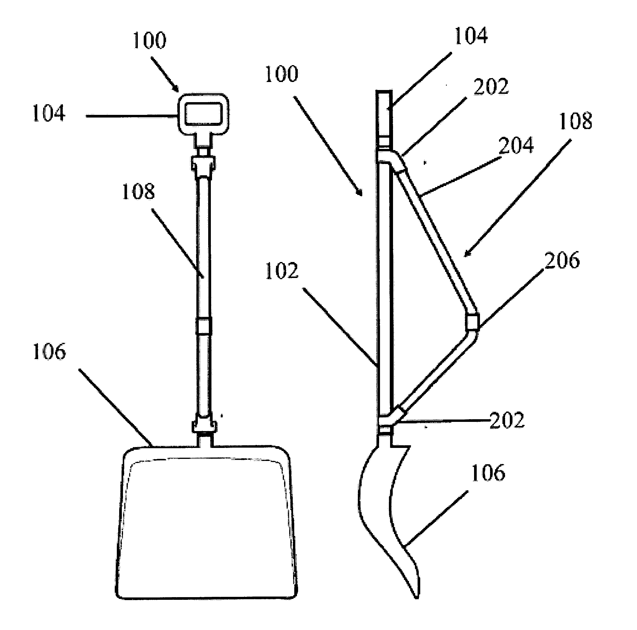
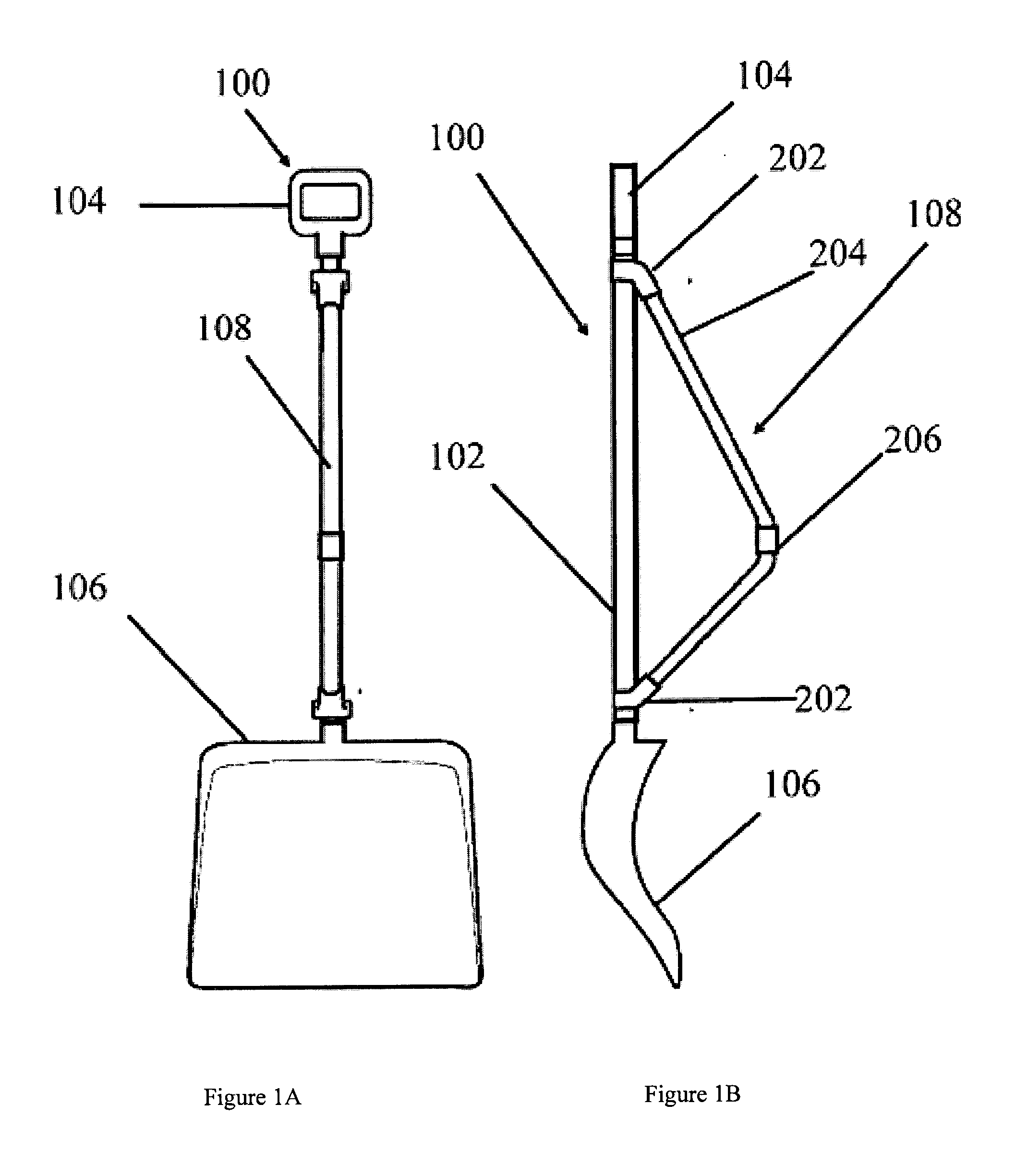
[0034]Referring now to FIGS. 1A and 1B, the standard snow shovel 100 consists of a wide blade 106 for scooping or shoveling snow, a long straight shaft or neck 102, and a grip or handle 104 at the far end of the neck 102 from the shovel blade ...


PUM


Abstract

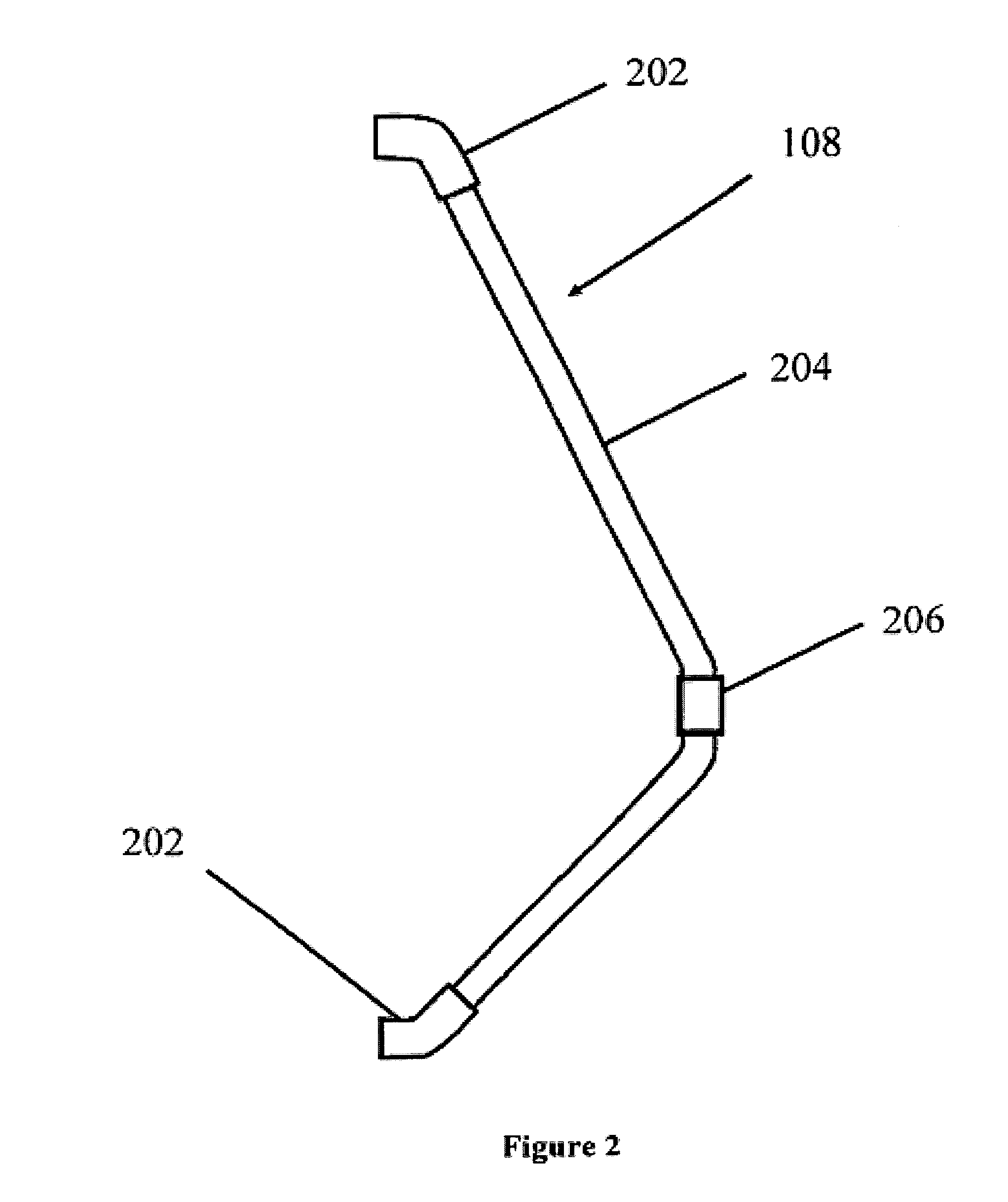
An attachment to a conventional snow shovel functions as an auxiliary handle and as a connector to a second snow shovel. When oriented substantially perpendicular to the shovel blade, the attachment functions as an auxiliary handle. The attachment connects to the shovel near the intersection of 1) the blade and neck and 2) the neck and handle. In this embodiment, the auxiliary handle functions as a cradle in which to rotate the shovel to dump snow more easily. The attachment may also be used to combine two shovels to form a plow. The attachment connects to a first shovel at the same two points as in the first configuration. In the same way, another attachment connects to the neck of a second shovel. The two attachments connect to each other at a third attachment point along the body of the attachments, creating a plow formed by the adjacent shovel blades.

Description

CROSS REFERENCE TO RELATED APPLICATIONS[0001]This application claims the benefit of U.S. Provisional Application No. 61 / 726,732 Snow Shovel Attachment, filed Nov. 15, 2012.BACKGROUND[0002]Manually removing snow from sidewalks and drive ways is time-consuming and exhausting. Shoveling can be a dangerous activity, in part because of the strenuous, physical motions required to bend, scoop the snow, lift the load, and then dump the snow. The repetitive motions and strenuous nature of shoveling may result in bodily injuries, especially to the back; overexertion; and even heart failure.[0003]A standard shovel requires significant bending to scoop the snow, causing the user to practice unsafe positions across a large range of back movements, including a twisting motion in the lower back of a shovel user. Despite the progress that ergonomic shovels have made in reducing some strain to the back, dumping the snow still required the user to employ awkward body positions, including twisting the...

Claims


Application Information

Patent Timeline
Patent Type & Authority Applications(United States)
IPC IPC(8): A01B1/02E01H5/06E01H5/02
CPCA01B1/026E01H5/061E01H5/02
Inventor STACHOWSKI, BREANNA L.
Owner STACHOWSKI BREANNA L
Learn More