
Rf-photonic system for acoustic and/or vibrational sensing using optical fiber and method thereof

Active Publication Date: 2014-05-15
ARMY US SEC THE
View PDF3 Cites 19 Cited by
  • Summary
  • Abstract
  • Description
  • Claims
  • Application Information

AI Technical Summary

Benefits of technology

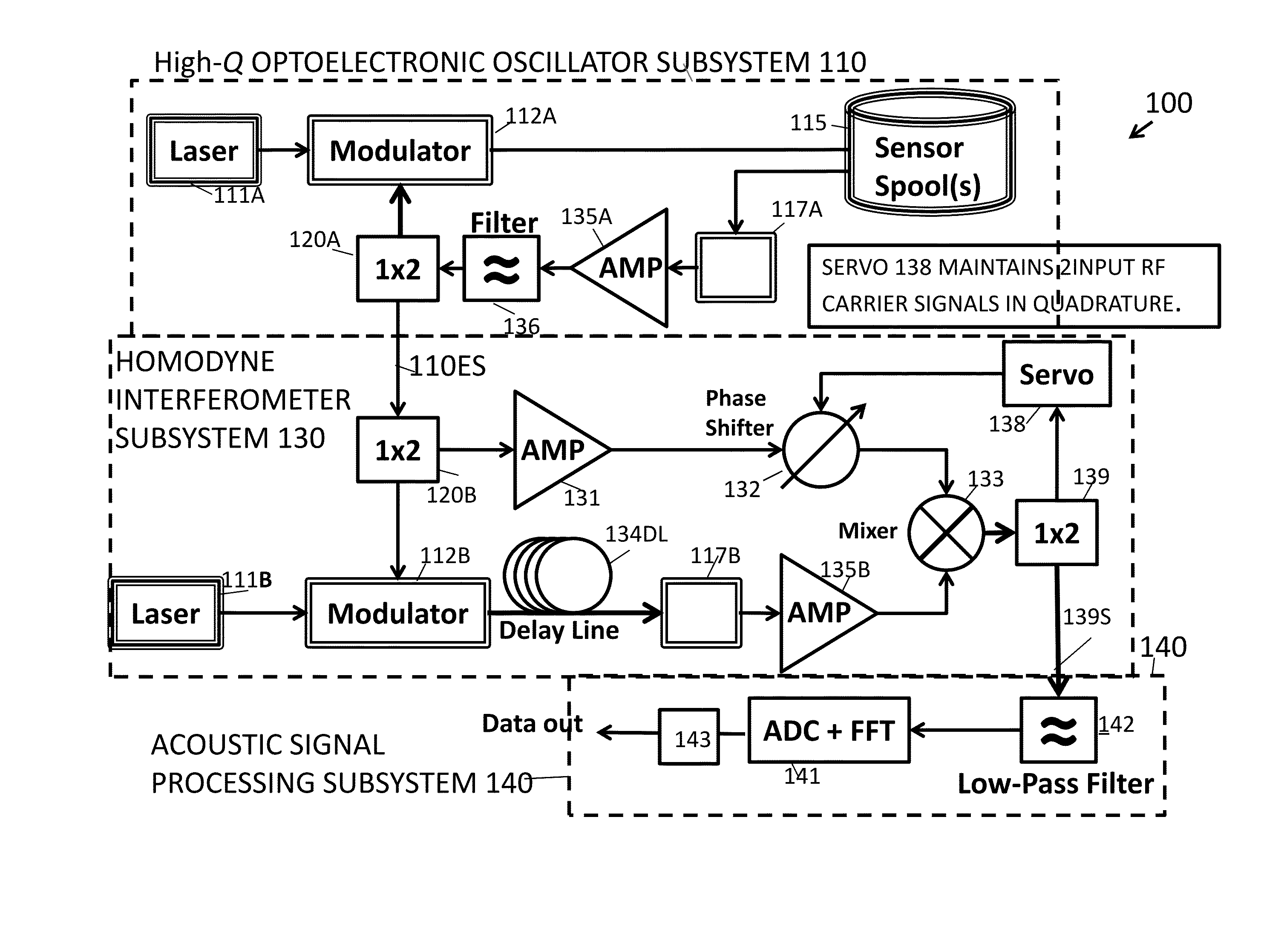
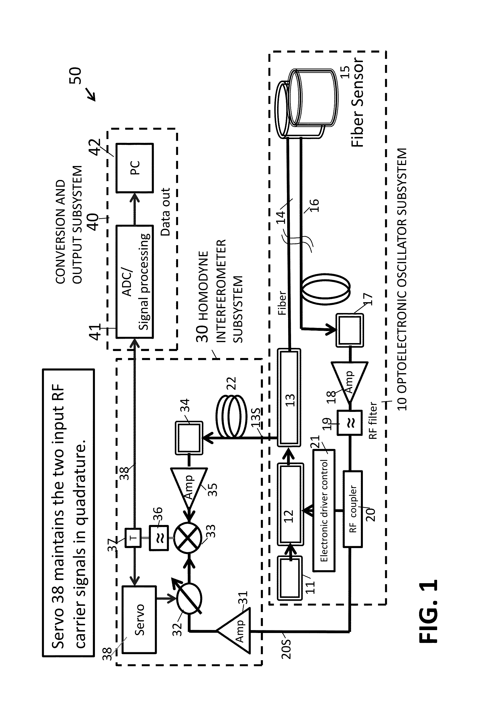
The present invention is a system for sensing vibrations and acoustic signals in a target area. The system includes an optoelectronic oscillator, a circuit for removal of carrier frequency, a sensor, and a signal processor. The optoelectronic oscillator generates a carrier signal with a modulator and sends it through an optical fiber to the sensor. The sensor receives the carrier signal and creates sideband signals, which are then received by the RF coupler and processed by the signal processor to detect the vibrations and acoustic signals. The system can be used in various applications such as detecting vibrations caused by vehicles, equipment, or humans. The sensor can be a spool of optical fiber with a receiving surface that detects the vibrations created by the target area. The technical effects of the invention include improved sensitivity, reduced interference, and improved detection and classification of vibrational and acoustic signals.

Problems solved by technology

Existing photonic sensing systems include fiber-based acoustic sensor techniques that require deployment and installation of a long optical fiber close to the area of interest and may only sense the activity very close to the fiber and may not provide any spectrum information.

Method used


Image

  • Rf-photonic system for acoustic and/or vibrational sensing using optical fiber and method thereof
  • Rf-photonic system for acoustic and/or vibrational sensing using optical fiber and method thereof
  • Rf-photonic system for acoustic and/or vibrational sensing using optical fiber and method thereof

Examples


Embodiment Construction

[0038]The embodiments herein and the various features and advantageous details thereof are explained more fully with reference to the non-limiting embodiments that are illustrated in the accompanying drawings and detailed in the following description. Descriptions of well-known components and processing techniques are omitted so as to not unnecessarily obscure the embodiments herein. The examples used herein are intended merely to facilitate an understanding of ways in which the embodiments herein may be practiced and to further enable those of skill in the art to practice the embodiments herein. Accordingly, the examples should not be construed as limiting the scope of the embodiments herein.

[0039]The embodiments of the invention and the various features and advantageous details thereof are explained more fully with reference to the non-limiting embodiments that are illustrated in the accompanying drawings and detailed in the following description. It should be noted that the featu...


PUM


Abstract

A method and system comprising:an optoelectronic oscillator comprising a light generator, a modulator, and at least one optical fiber, the optoelectronic oscillator operating to send a modulated carrier signal through the optical fiber into a target area and receive the return signal;a circuit for removal of the carrier frequency operatively connected to the oscillator comprising at least one phase shifter; at least one mixer operatively connected to the at least one phase shifter; at least control circuit operatively connected the at least one mixer and the at least one phase shifter for controlling the phase shifter and operating to cancel signals other than the sideband signals;a signal processor for processing the sideband signals to detect acoustical and / or vibrational signals from the target area. The method comprises sensing vibrational and / or acoustical signals for detection of acoustical and / or vibrational signals in the target area.

Description

CROSS REFERENCE TO RELATED APPLICATIONS[0001]This application claims priority to and is a continuation-in-part of U.S. application Ser. No. 13 / 677,659 (ARL 08-40), entitled “Method and Apparatus for Analyzing the Spectrum of Radio-Frequency Signals Using a Fiber Optic Recirculation Loop,” filed Nov. 15, 2012, by Ming-Chiang Li, and Weimin Zhou, herein incorporated by reference.STATEMENT OF GOVERNMENT INTEREST[0002]The embodiments herein may be manufactured, used, and / or licensed by or for the United States Government without the payment of royalties thereon.BACKGROUND OF THE INVENTION[0003]Optoelectronic systems include photonic radio frequency (RF) systems that incorporate photonic (optical) technology into traditional RF systems. Optical technology offers the advantage of remote capability and relative immunity to electromagnetic interference. Oscillator components for photonic radio frequency communication systems are known in the art, such as for example, U.S. Pat. No. 5,723,856...

Claims


Application Information

Patent Timeline
IPC IPC(8): G01N29/24
CPCG01N29/24
Inventor ZHOU, WEIMINOKUSAGA, OLUKAYODECAHILL, JAMES P
Owner ARMY US SEC THE
Learn More