On-line tunnel deformation monitoring system based on image analysis and its application

Inactive Publication Date: 2014-05-08
TONGJI UNIV
View PDF18 Cites 24 Cited by
  • Summary
  • Abstract
  • Description
  • Claims
  • Application Information

AI Technical Summary

Benefits of technology

The present invention is an online tunnel deformation monitoring system that uses image analysis to detect and measure changes in the condition of tunnels. The system is easy to use, can provide real-time monitoring and automatic warning, and can also save historical photos for future analysis. The system uses a central control computer that filters and adjusts the output of photos based on the level of image variation. Overall, the invention overcomes the shortcomings of existing technologies and offers a more efficient and effective solution for monitoring tunnel deformations.

Problems solved by technology

Currently, in the Mainland, manual field measurement is often adopted for the measurement of tunnel deformation, which is on the one hand of low efficiency, and on the other hand influenced greatly by human factors with big measurement errors and no realization of on-line monitoring or automatic warning.
However, the existing on-line tunnel deformation monitoring systems generally have defects such as high realization costs and poor monitoring schedules.

Method used


Image

  • On-line tunnel deformation monitoring system based on image analysis and its application
  • On-line tunnel deformation monitoring system based on image analysis and its application
  • On-line tunnel deformation monitoring system based on image analysis and its application

Examples


embodiments

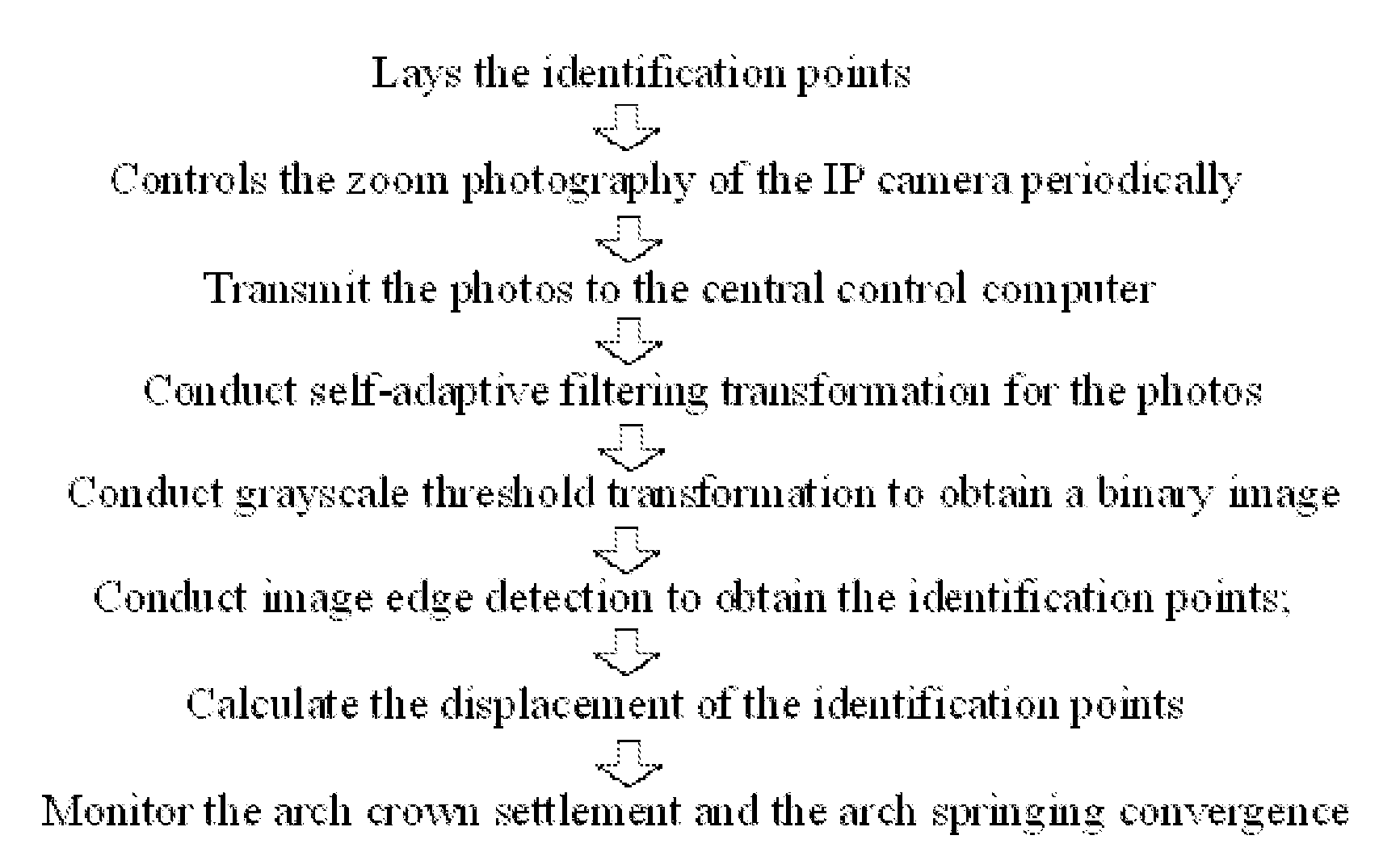
[0033]An on-line tunnel deformation monitoring system based on image analysis, characterized in that it comprises identification points, an IP camera, a central control computer and a transmission network, wherein the identification points is laid such that they point at the installation location of the IP camera and the transmission network is used to connect the IP camera and the central control computer.

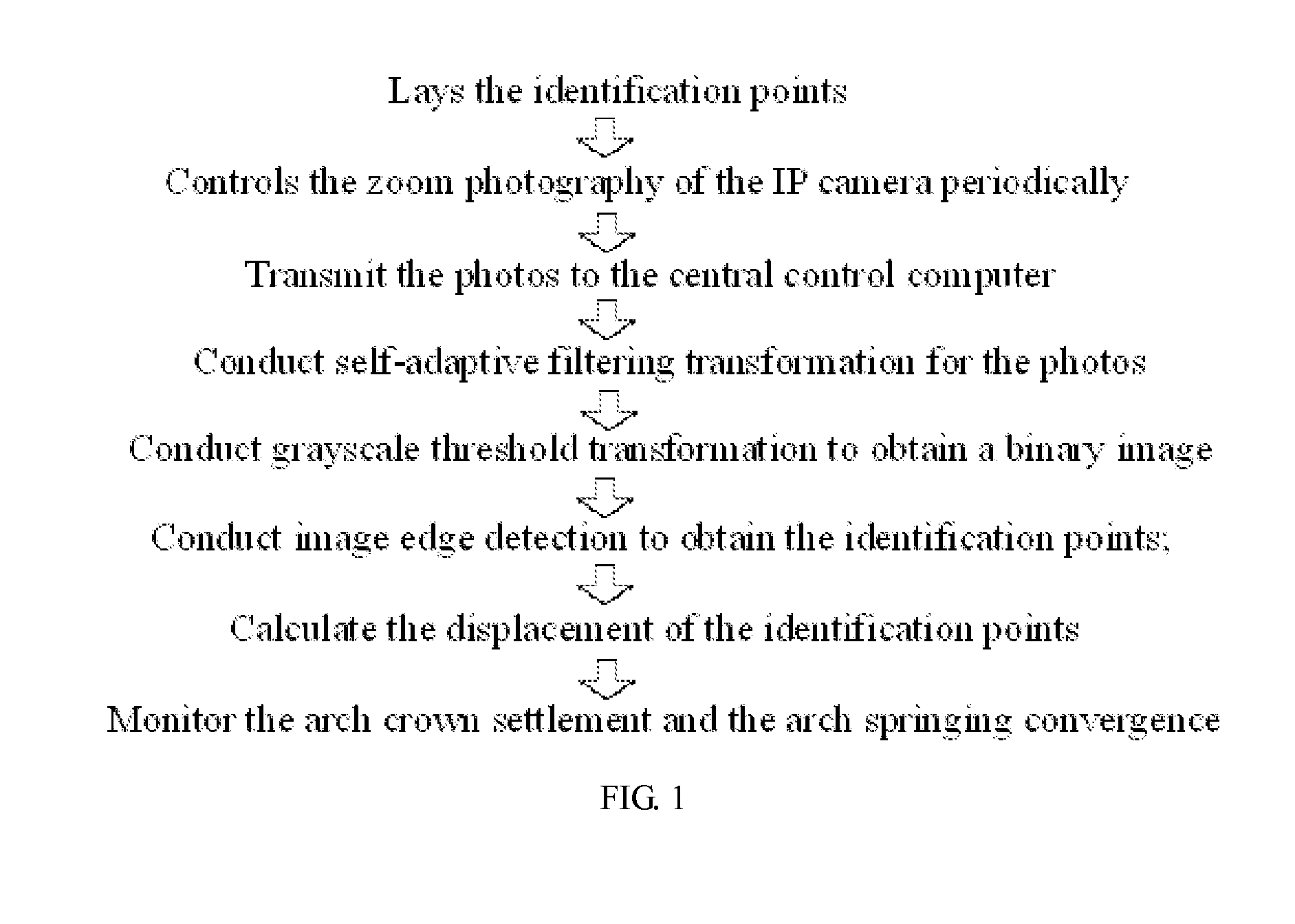
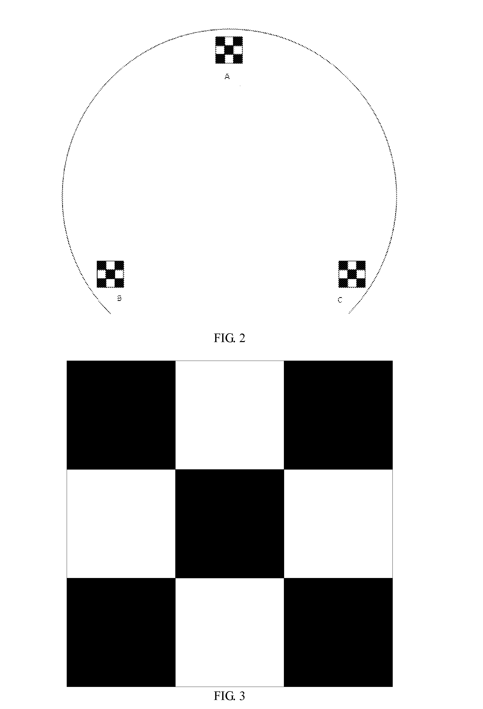
[0034]As shown in FIG. 2, the identification points consist of 2 cm×2 cm squares with 3 rows and 3 columns in continuous arrangement, wherein the colours of each row from top to bottom are black-white-black, white-black-white, and black-white-black respectively. 3 identification points are laid in total at the arch crown and the right and left arch springing points respectively in the same vertical elevation.

[0035]The IP camera is perpendicular to the installation elevation of the identification points and fitted with LED fill lamps (white light). The image resolution of the IP ca...


PUM


Abstract

An on-line tunnel deformation monitoring system based on image analysis and its application comprises identification points, an IP camera, a central control computer, as well as a transmission network and the application of the system includes the following steps: 1) lay the identification points; 2) the central control computer controls the zoom photography of the IP camera periodically; 3) the IP camera transmits the photos to the central control computer; 4) the central control computer conducts self-adaptive filtering transformation for the photos; 5) the central control computer conducts grayscale threshold transformation; 6) the central control computer conducts image edge detection to obtain the identification points; 7) calculation of the arch crown settlement displacement and the arch springing convergence displacement of the identification points; 8) judge whether the arch crown settlement displacement and the arch springing convergence displacement are both less than the set thresholds, and if they are, return to Step 2), otherwise give an alarm.

Description

BACKGROUND OF THE INVENTION[0001]1. Technical Field[0002]The present invention relates to relevant technologies of an on-line tunnel deformation monitoring system, and especially to an on-line tunnel deformation monitoring system based on image analysis and its application.[0003]2. Description of Related Art[0004]Currently, in the Mainland, manual field measurement is often adopted for the measurement of tunnel deformation, which is on the one hand of low efficiency, and on the other hand influenced greatly by human factors with big measurement errors and no realization of on-line monitoring or automatic warning.[0005]With the continuous improvement of computer performance, the enhancement of computer image processing performance, the appearance of high-resolution digital products, and the generation of powerful image processing & calculation software, the development and application of the deformation measurement based on digital photography in geotechnical engineering has become p...

Claims


Application Information

Patent Timeline
IPC IPC(8): H04N7/18
CPCH04N7/183G01C15/04G01M5/0025G01M5/0091G01M11/081G06T7/0004G06T2207/30132G06T2207/30208E21F17/18G06V20/52
Inventor ZHU, HEHUALIU, XUEZENGSANG, YUNLONG
Owner TONGJI UNIV
Why Eureka
Try Eureka