
System of a Surveillance Camera For Identifying And Incapacitating Dangerous Intruders

a surveillance camera and system technology, applied in the field of surveillance cameras, can solve problems such as physical violence of cashiers, the risk of individuals attempting to acquire items without paying, and the risk of further business robbery

Inactive Publication Date: 2014-05-01
BUCKNOR VALENTINE A
View PDF8 Cites 24 Cited by
  • Summary
  • Abstract
  • Description
  • Claims
  • Application Information

AI Technical Summary

Benefits of technology

The present invention is a surveillance camera system that identifies and prepares to incapacitate dangerous intruders. The system uses a camera to capture images and videos of the intruder, and an infrared camera to detect their presence. The system also includes an electrical stun gun that is triggered by the camera and a threat detection sensor. The camera system is designed to autonomously identify a dangerous intruder and prepare to fire the stun gun at the push of a button. The invention helps to prevent theft and physical harm to businesses and their employees.

Problems solved by technology

In any place of business, especially one that sells items of high value or that process a significant amount of cash transactions, there is a risk of individuals attempting to acquire items without paying.
In addition to having their goods stolen, a further risk to a business is being robbed by demanding the cashier empty the cash register and threatening the cashier with physical violence if the cashier does not comply.
However, there is often little time to pick up and ready the weapon, as the intruder is already in a heightened state of awareness and preparation, while the person working the counter must process the fact that there is a dangerous intruder and must drastically and quickly change their state of mind in order to react appropriately, and is likely to be unable to reach the weapon due to raising their hands in surrender.

Method used


Image

  • System of a Surveillance Camera For Identifying And Incapacitating Dangerous Intruders
  • System of a Surveillance Camera For Identifying And Incapacitating Dangerous Intruders
  • System of a Surveillance Camera For Identifying And Incapacitating Dangerous Intruders

Examples


Embodiment Construction

[0013]All illustrations of the drawings are for the purpose of describing selected versions of the present invention and are not intended to limit the scope of the present invention.

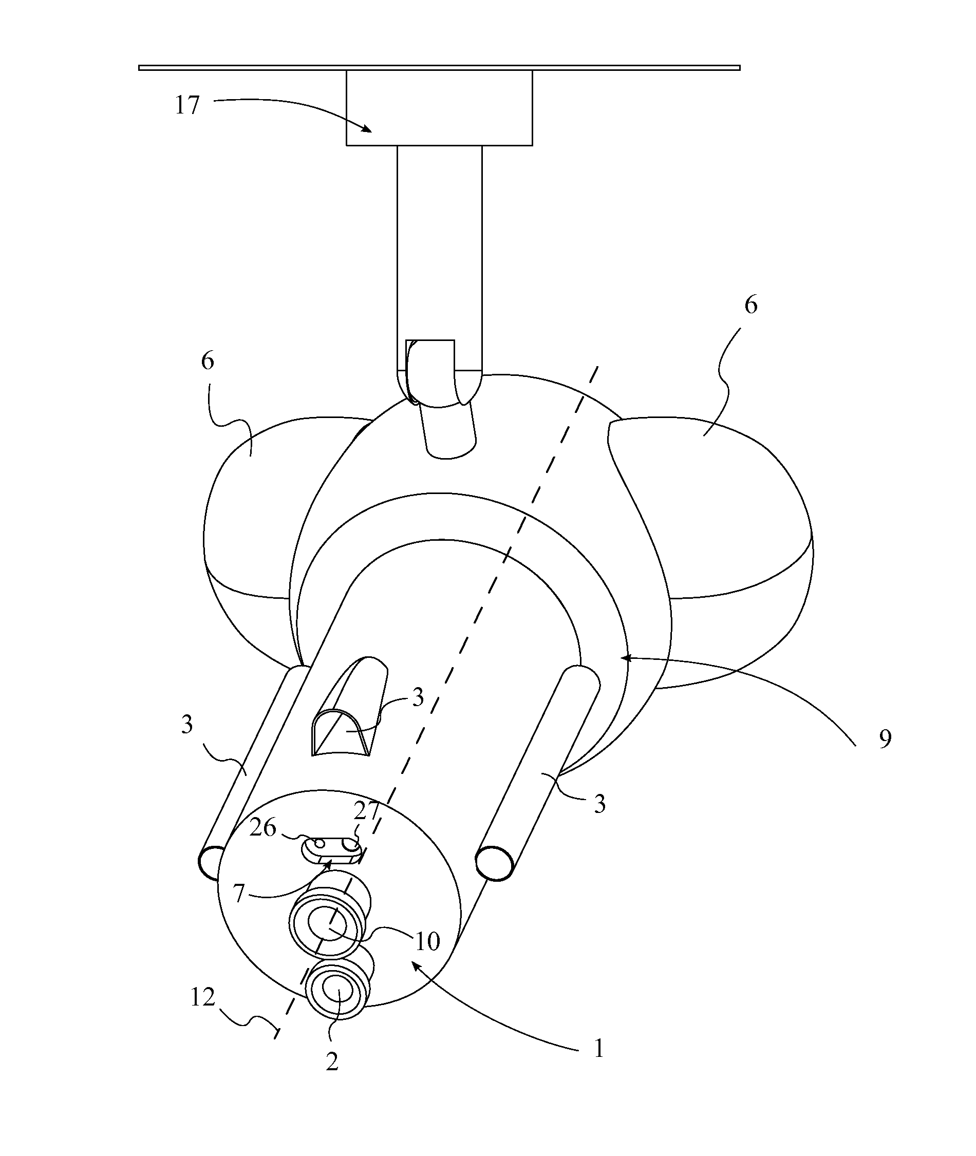
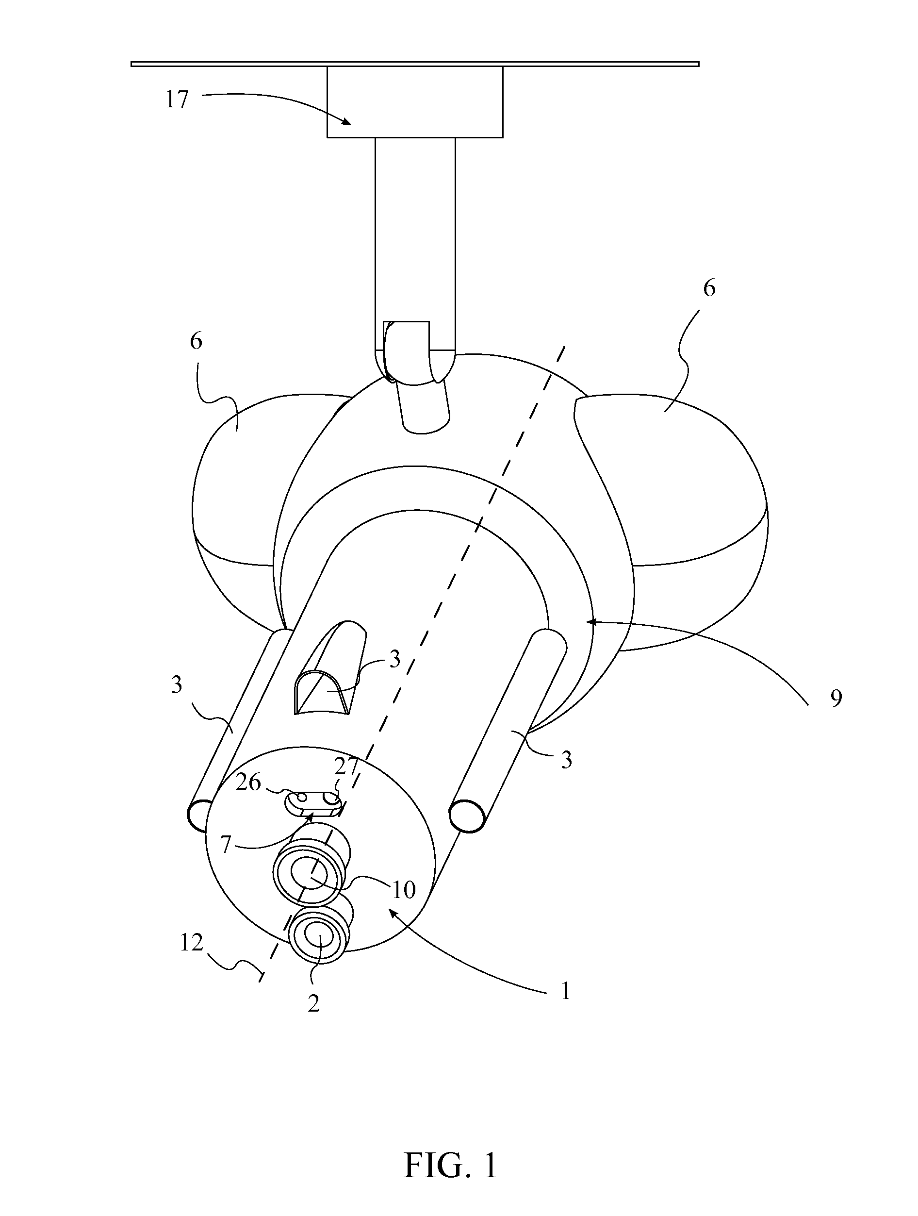
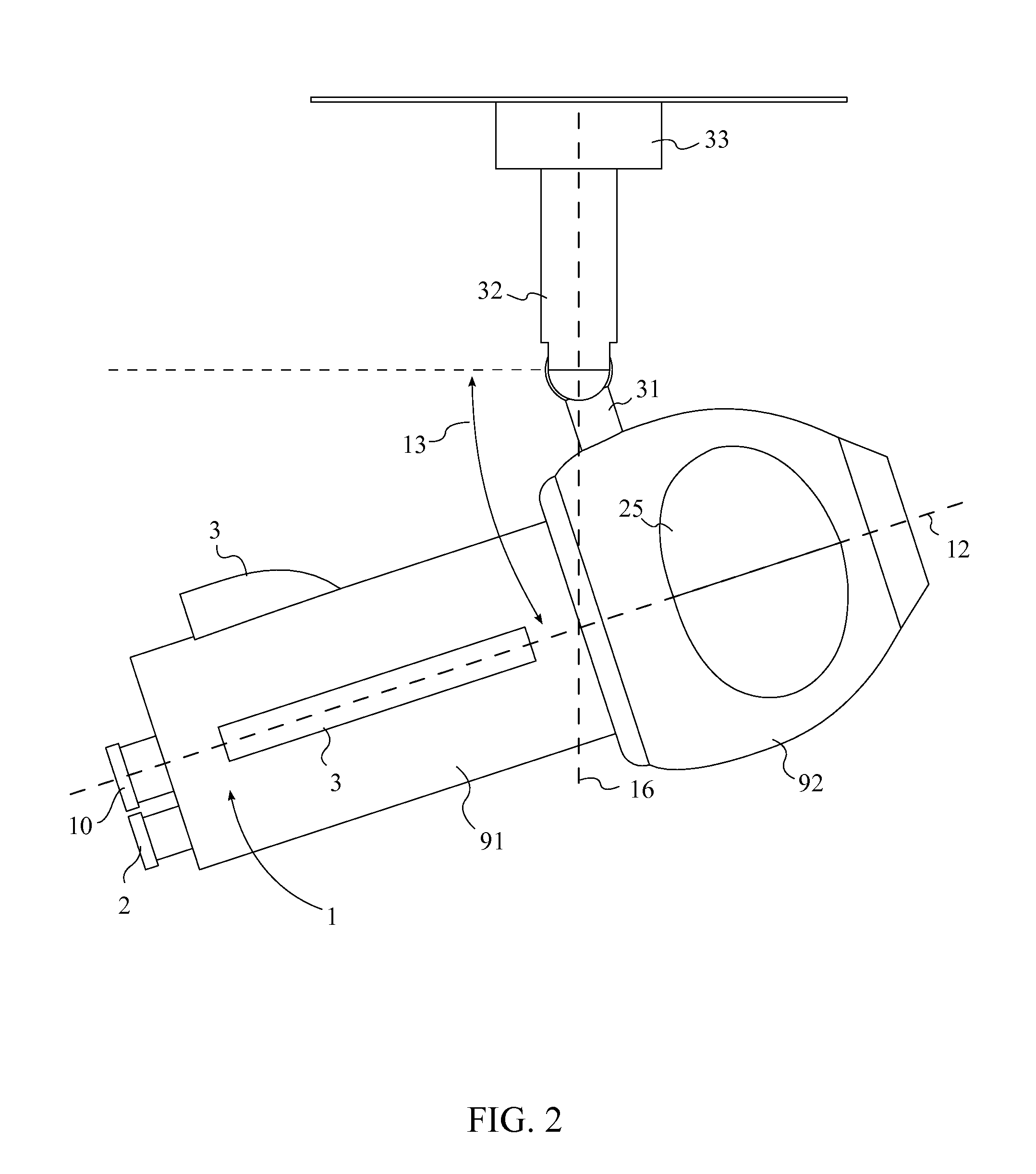
[0014]The present invention generally comprises a camera 1, an infrared camera 2, an electrical stun gun 3, a threat detection sensor 4, a remote control 5, a threat information storage module 6, a laser rangefinder 7, and a data processing module 8.

[0015]Referring to FIGS. 1-3, the camera 1 utilizes well-known technology to capture and record video and still images and to adjust the angle of orientation of the camera 1 in order to facilitate the broadest area of surveillance possible. The camera 1 comprises a housing 9, a lens 10, an image capturing chip 11, a central axis 12, an inclination angle 13, an inclination axis 14, an azimuth angle 15, an azimuth axis 16, a mount 17, an inclination motor 18, an azimuth motor 19, and a camera wireless radio communication device 20.

[0016]The housing 9 is the out...


PUM


Abstract

A system of a surveillance camera for identifying and incapacitating dangerous intruders is a standard video camera with an additional infrared camera and an electrical stun gun. A data processing module in the camera utilizes body detection and tracking software to scan images received from the camera for human bodies, and a threat detection sensor communicates with the data processing module in order to identify a specific human body in the images as a threat. Once a threat is identified, the camera continually repositions itself so that at any given moment, a remote control can trigger the deployment of the electrical stun gun to incapacitate the threat. The data processing module also scans the facial and retina characteristics of the threat and stores the information in an information storage module at the back of the camera.

Description

FIELD OF THE INVENTION[0001]The present invention relates generally to security systems. More particularly, the present invention relates to a surveillance camera system that identifies and incapacitates dangerous intruders.BACKGROUND OF THE INVENTION[0002]In any place of business, especially one that sells items of high value or that process a significant amount of cash transactions, there is a risk of individuals attempting to acquire items without paying. The majority of stores employ loss prevention techniques, including surveillance by video cameras, radio frequency or electromagnet anti-shoplifting devices, and security personnel. In addition to having their goods stolen, a further risk to a business is being robbed by demanding the cashier empty the cash register and threatening the cashier with physical violence if the cashier does not comply. To mitigate such a situation, business owners often keep a firearm behind the counter to allow the cashier or business owner to attem...

Claims


Application Information

Patent Timeline
IPC IPC(8): H04N7/18
CPCH04N7/18G08B13/19608G08B13/19619G08B15/005G06V40/10G06V20/52H04N23/50H04N23/661H04N23/23H04N5/33
Inventor BUCKNOR, VALENTINE A.
Owner BUCKNOR VALENTINE A
Learn More