
Mounting structure of assist grip

a technology of assist grip and mounting structure, which is applied in the direction of roofs, monocoque constructions, vehicle arrangements, etc., can solve the problems of excessive impact force, achieve the effects of avoiding excessive stress concentration, and easy formation of weak parts

Inactive Publication Date: 2014-05-01
TOYOTA IND CORP +1
View PDF8 Cites 0 Cited by
  • Summary
  • Abstract
  • Description
  • Claims
  • Application Information

AI Technical Summary

Benefits of technology

The present invention is aimed at providing a mounting structure for an assist grip that has the ability to absorb high impact force. It achieves this by notching a weak portion in the structure, which triggers buckling when impact force is applied. The notched shape is designed to be a curve to avoid excessive stress concentration. This results in a high impact absorption capacity for the mounting structure of the assist grip.

Problems solved by technology

However, in the above-described mounting structure of the assist grip, when excessive impact force is applied, legs are vigorously bent at a relatively early stage, or when the legs of a bracket have high strength, the legs are seldom deformed, thereby resulting in the excessive impact force.

Method used


Image

  • Mounting structure of assist grip
  • Mounting structure of assist grip
  • Mounting structure of assist grip

Examples


Embodiment Construction

[0024]Hereinafter, referring to the accompanying drawings, preferred embodiments of the present invention will be described in detail. In the description, the same reference numerals are given to the same elements or elements having the same function, and the repeated description will be omitted.

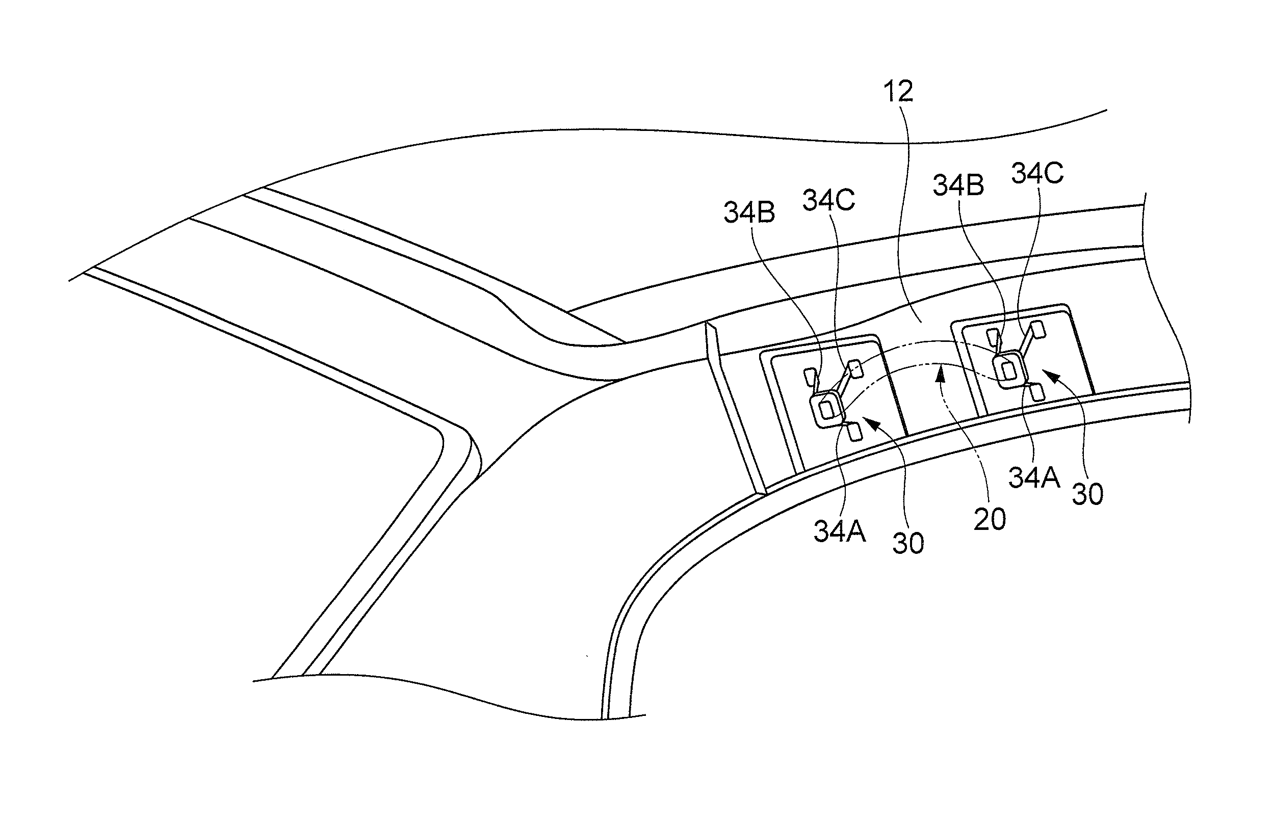
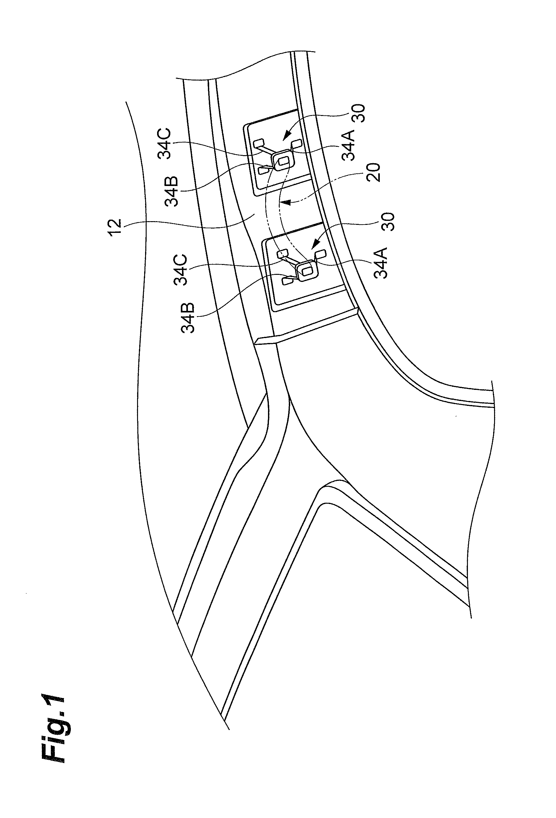
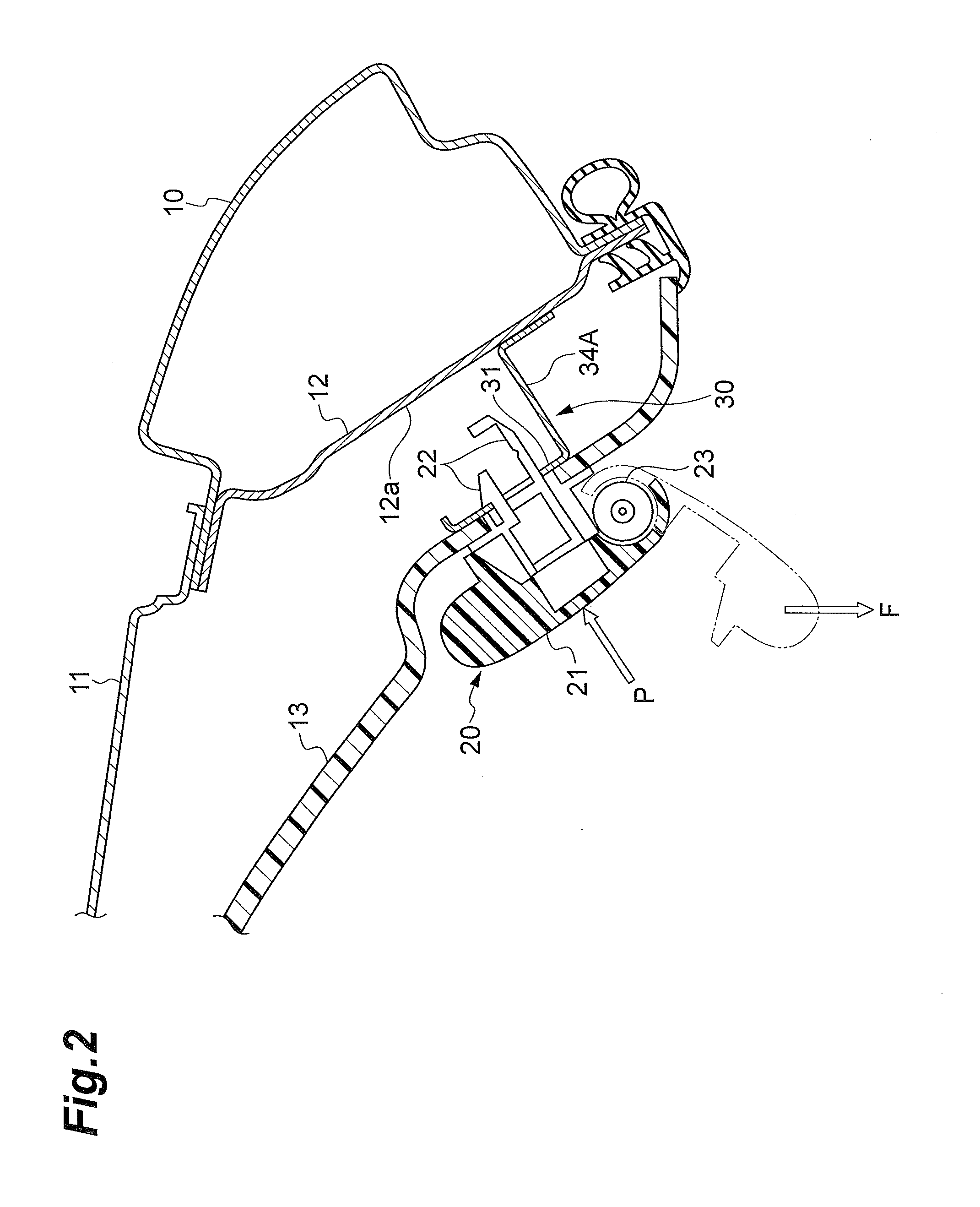
[0025]FIGS. 1 and 2 illustrate a mounting structure of an assist grip according to an embodiment of the present invention. An assist grip 20 is mounted on a roof side rail inner panel 12 in a side portion of a ceiling inside a passenger compartment of a vehicle via a pair of brackets 30.

[0026]More specifically, a mounting position of the bracket 30 is an inner surface 12a inside the passenger compartment of the roof side rail inner panel 12 (rail side panel coupled to a side portion of a roof panel 11) which forms a closed sectional-shaped portion by using a side body outer panel 10.

[0027]For example, the assist grip 20 includes a U-shaped grip main body 21 which is integrally molded with a ...


PUM


Abstract

Total four notched portions, two for each of both edges, are formed in a lateral leg to which a tensile load is applied when an assist grip is normally used. In an extending direction of the lateral leg, a position of the notched portion and a position of the notched portion are different from each other. Therefore, if excessive impact force is applied to the assist grip and a compression load is applied to the lateral leg, the notched portion is bent and the lateral leg buckles while being twisted. In this case, as compared to a case where the legs buckle by being bent so that the legs are overlapped with each other, the impact force is effectively absorbed.

Description

BACKGROUND OF THE INVENTION[0001]1. Field of the Invention[0002]The present invention relates to a mounting structure of an assist grip in a vehicle such as an automobile.[0003]2. Related Background Art[0004]In order to assist an occupant in getting in and out of a vehicle, the vehicle such as an automobile is provided with an assist grip disposed on a ceiling inside a passenger compartment. For example, Japanese Unexamined Patent Application Publication No. 2003-137012 (Patent Literature 1) discloses a technology for mounting the assist grip on a vehicle body such as a roof panel or a side panel.[0005]A mounting structure of the assist grip disclosed in Patent Literature 1 employs a bracket provided with three legs, in which the assist grip is mounted on a main body of the bracket and each leg is mounted on a roof side rail inner panel.[0006]According to the invention disclosed in Patent Literature 1, if excessive impact force is applied to the assist grip in a direction from an in...

Claims


Application Information

Patent Timeline
Patent Type & Authority Applications(United States)
IPC IPC(8): B60N3/02
CPCB60N3/026
Inventor INOUE, MASASHI
Owner TOYOTA IND CORP
Learn More