
Light emitting diode devices, method of manufacture, uses thereof

a technology of light-emitting diodes and diodes, which is applied in the field of light-emitting diodes (led) devices, can solve the problems of reducing light output, reducing the yellowness index, and reducing the time of heat shortening significantly, so as to reduce the photodegradation of a component and increase the yellowness index

Active Publication Date: 2014-05-01
SABIC GLOBAL TECH BV
View PDF10 Cites 19 Cited by
  • Summary
  • Abstract
  • Description
  • Claims
  • Application Information

AI Technical Summary

Benefits of technology

The present invention relates to a composition that uses specific types of bisphenol A polycarbonate. These polycarbonates have specific properties that provide advantages in the composition. The use of these polycarbonates can provide a more stable and reliable composition. The polycarbonates can be made using a special process that ensures high purity and low sulfur levels. This results in a composition that is more aesthetically pleasing and has better performance properties. The use of these specific polycarbonates can also reduce the risk of negative side effects or reactions when used in the composition. Overall, the present invention provides a more effective and safer composition using specific types of polycarbonate.

Problems solved by technology

However, heat can shorten this time significantly.
This causes stress on the material for LED components, which may lead to early failure of the devices.
The most common symptom of LED failure is the gradual lowering of light output and loss of efficiency due to the yellowing of LED housing materials.
Sudden failures, although rare, can occur as well.

Method used


Image

  • Light emitting diode devices, method of manufacture, uses thereof
  • Light emitting diode devices, method of manufacture, uses thereof
  • Light emitting diode devices, method of manufacture, uses thereof

Examples


example 1

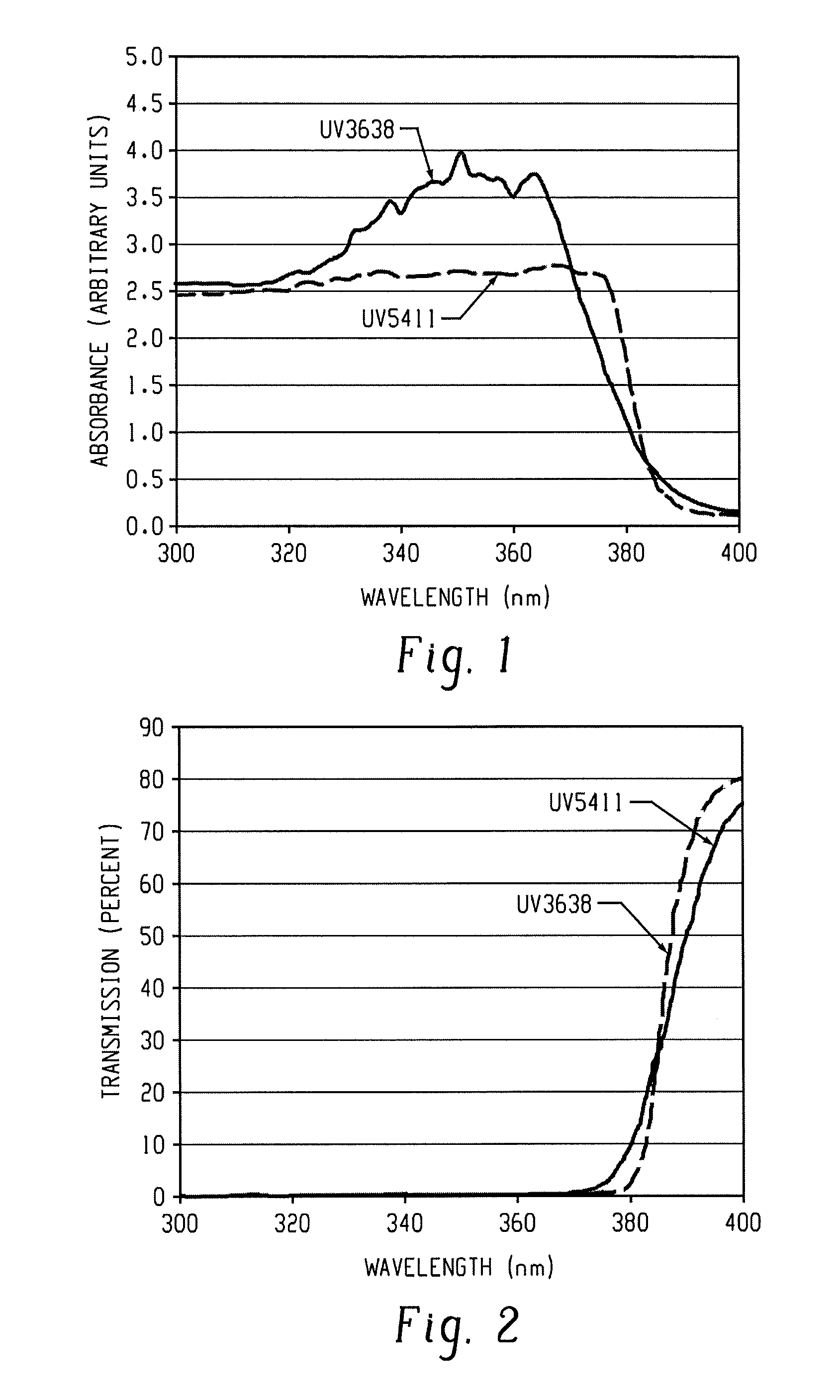
[0134]This example demonstrates that UV3638-containing polycarbonate compositions can have the same UV performance as UV5411-containing polycarbonate compositions, while at the same time, UV-3638 containing polycarbonate compositions absorb less light having a wavelength above about 370 nm. FIGS. 1 and 2 show data for compositions within the ranges shown in Table 2.

TABLE 2Component (wt %)UV5411 PC1UV3638 PC1PC1 97.3-99.97 97.3-99.97PC2Stabilizer / antioxidant0.01-0.2 0.01-0.2 Mold release agent0.01-0.2 0.01-0.2 Flame retardant  0-2.0  0-2.0packageUV5411 (wt %)0.01-0.3 UV3638 (wt %)0.01-0.3 

[0135]Absorbance and transmission of UV5411- and UV3638-containing polycarbonate compositions are illustrated in FIGS. 1 and 2. FIG. 1 shows that the UV5411-containing polycarbonate compositions has higher absorbance when the excitation source is greater than 370 nm as compared to the UV3638-containing polycarbonate composition. FIG. 2 shows that below 370 nm no UV light is transmitted for either th...

example 2

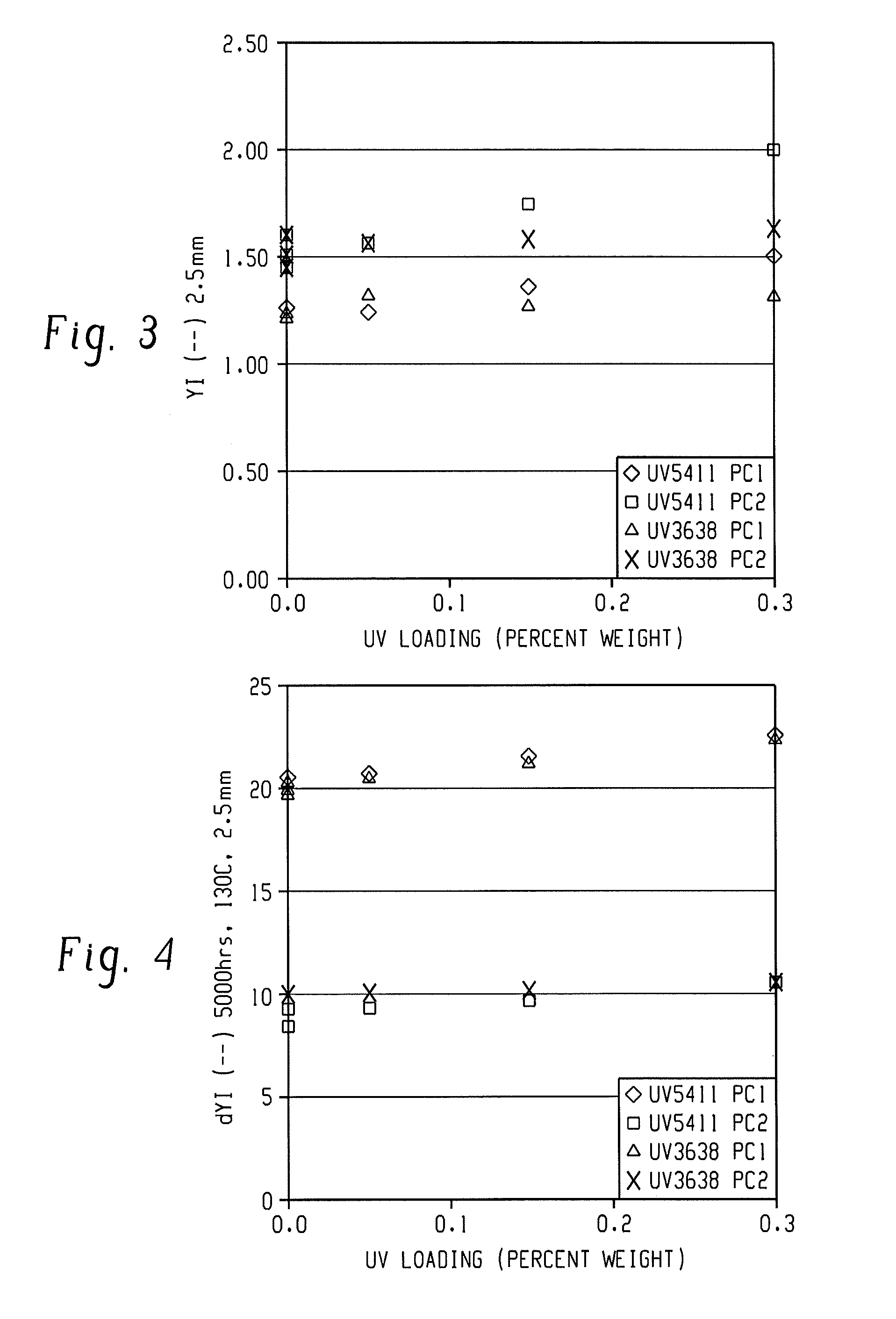
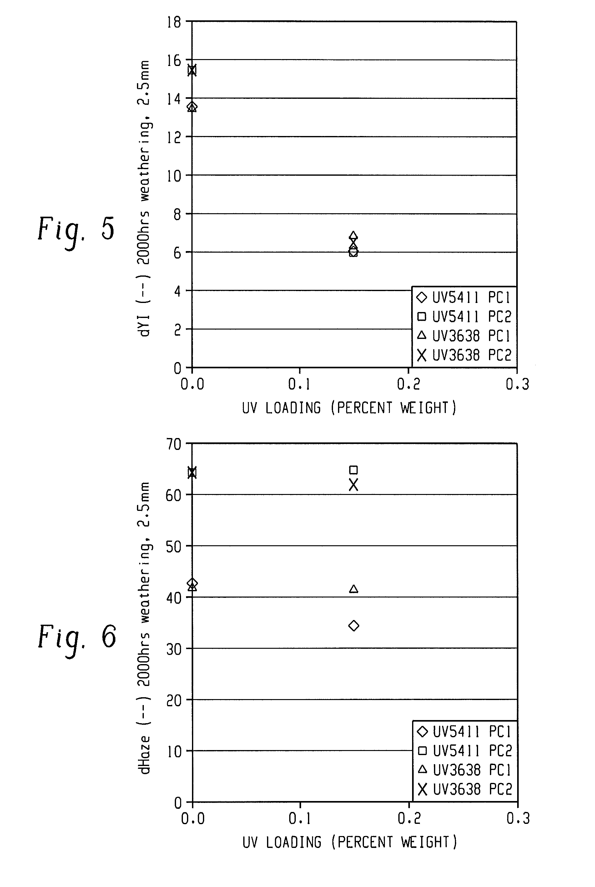
[0136]The optical performances of various UV5411- and UV3638-containing polycarbonate compositions before and after weathering are compared. The test results are presented in FIGS. 3, 4, 5, and 6, which show data for compositions within the ranges shown in Table 3.

TABLE 3ComponentUV5411UV5411UV3638UV3638(wt %)PC1PC2PC1PC2PC1 97.3-99.97 97.3-99.97PC2 97.3-99.9797.3 99.97Stabilizer / 0.01-0.20.01-0.20.01-0.20.01-0.2antioxidantMold release0.01-0.20.01-0.20.01-0.20.01-0.2agentFlame retardant  0-2.0  0-2.0  0-2.0  0-2.0packageUV54110.01-0.30.01-0.3UV36380.01-0.30.01-0.3

[0137]FIG. 3 shows that before weathering, above about 0.25 wt. %, the UV3638-containing polycarbonate composition based on PC1 is less yellow than the same UV5411-containing polycarbonate compositions. The trend is similar in compositions based on PC-2. In those compositions, above about 0.13 wt. %, the UV3638-containing polycarbonate composition based on PC2 is less yellow than the same UV5411-containing polycarbonate comp...


PUM

PropertyMeasurementUnit
thicknessaaaaaaaaaa
yellowness indexaaaaaaaaaa
wt. %aaaaaaaaaa

Abstract

A light emitting diode lighting device contains a light emitting diode and a lighting device component, wherein the device component comprises a polycarbonate composition comprising a bisphenol A polycarbonate; and 2,2′-(1,4-phenylene)bis(4H-3,1-benzoxazin-4-one) in an amount effective to provide a composition wherein a molded sample of the composition has a UL94 rating of V-2 or better at a thickness of 0.9 mm; an absorbance of less than 2 a.u. in the region of 370 to 380 nanometers; and an increase in yellowness index (ΔYI) of 12 or less at 2.5 mm thickness after heat aging at 130° C. for 5,000 hours.

Description

CROSS REFERENCE TO RELATED APPLICATIONS[0001]The present application claims priority to U.S. Provisional Application Ser. No. 61 / 718,400, filed Oct. 25, 2012, the contents of which are incorporated herein by reference in their entirety.BACKGROUND[0002]This disclosure is directed to light emitting diode (LED) devices and materials for LED device components, and in particular to LED lighting devices comprising polycarbonates.[0003]LEDs are semiconductor devices that emit incoherent narrow-spectrum light when electrically biased in the forward direction of their p-n junctions (boundary between P-type and N-type semiconductor), and are thus referred to as solid-state lighting devices.[0004]LEDs can be used in applications as diverse as aviation lighting, automotive lighting, advertising, indoor lighting and traffic signals. Recently, with the development of LED technology, LEDs are fast replacing incandescent and fluorescent lighting. Compared to other lighting devices, LED products off...

Claims


Application Information

Patent Timeline
Patent Type & Authority Applications(United States)
IPC IPC(8): H01L33/52B29D11/00
CPCH01L33/52B29D11/0074H01L33/56C08K5/357H01L33/501C08L69/00
Inventor VAN HEERBEEK, HENDRIKUS PETRUS CORNELISHUIJS, FRANKDE BROUWER, JOHANNESHEIN, CHRISTOPHER LUKE
Owner SABIC GLOBAL TECH BV
Learn More