
Optical subtraction of molecular dispersion signals enabled by differential optical dispersion spectroscopy

a technology of optical dispersion and molecular dispersion signals, applied in the field ofdifferential optical dispersion, can solve the problems of affecting measurement, slow evacuation process, reducing reliability and long-term stability of setup,

Active Publication Date: 2014-04-24
THE TRUSTEES FOR PRINCETON UNIV
View PDF4 Cites 5 Cited by
  • Summary
  • Abstract
  • Description
  • Claims
  • Application Information

AI Technical Summary

Benefits of technology

This patent describes an apparatus and method for differential optical dispersion using two samples. The apparatus includes a laser source, optical branches, and a detector. The method involves measuring the transmission and dispersion spectra of the samples and analyzing them to retrieve parameters such as temperature, pressure, and optical path length. The technical effect of this patent is to provide a reliable and accurate method for measuring optical properties of samples.

Problems solved by technology

In the second case, switching of the gas mixture inside the gas cell requires a complex gas handling, the cell evacuation process is slow, and any nonlinearity of the detector can also affect measurement results.
Due to unavoidable drifts in the system the slow gas exchange process will reduce reliability and long-term stability of the setup.

Method used


Image

  • Optical subtraction of molecular dispersion signals enabled by differential optical dispersion spectroscopy
  • Optical subtraction of molecular dispersion signals enabled by differential optical dispersion spectroscopy
  • Optical subtraction of molecular dispersion signals enabled by differential optical dispersion spectroscopy

Examples


Embodiment Construction

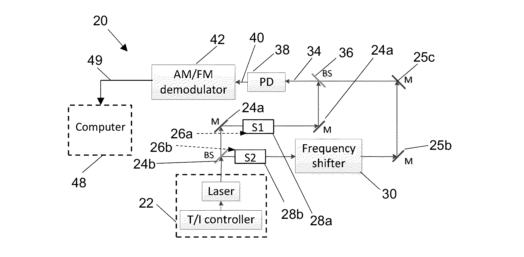
[0017]Disclosed are a method and apparatus for the optical subtraction of molecular dispersion signals enabled by differential optical dispersion spectroscopy (DODiS). Using the method and apparatus disclosed herein, two samples can be measured simultaneously in exactly the same conditions and using only one optical detector which provides enough information to characterize concentrations of the samples in both optical paths. FIG. 1a is block diagram of an apparatus 20 configured for differential / comparative analysis of two gas samples. The system is coupled to a single frequency chirped laser source 22 configured to generate laser radiation having a fundamental frequency. In this example a distributed feedback (DFB) quantum cascade laser (QCL) and T / I (temperature / current) controller was used. It should be understood that other laser sources may be used without departing from the scope of this disclosure. The laser radiation is divided into two beams (two optical branches) using be...


PUM

PropertyMeasurementUnit
frequencyaaaaaaaaaa
pressureaaaaaaaaaa
optical dispersionaaaaaaaaaa

Abstract

An apparatus and method for differential optical dispersion using a first sample and a second sample are disclosed. The apparatus includes a single frequency chirped laser source configured to generate a single frequency chirped laser beam. A first beam splitter is configured to split the single frequency chirped laser beam into first and second optical branches, the first sample being located in the first optical branch, the second sample being located in the second optical branch. A frequency shifter is located in the second optical branch, downstream of the second sample. A second beam splitter is configured to combine the first and second optical branches and generate a chirp-modulated mixed light beam. A square law detector is configured to detect the chirp-modulated mixed light beam and generate a heterodyne beatnote signal. A demodulator is configured for detection of the heterodyne beatnote signal to generate a transmission / differential optical dispersion spectrum.

Description

CROSS-REFERENCE TO PRIOR FILED APPLICATIONS[0001]This application claims priority to U.S. provisional application 61 / 715,982 filed on Oct. 19, 2012 which is incorporated herein in its entirety.STATEMENT REGARDING FEDERALLY SPONSORED RESEARCH OR DEVELOPMENT[0002]This invention was made with government support under National Science Foundation contract # CMMI-0954897. The government has certain rights in this invention.FIELD OF THE INVENTION[0003]The present disclosure generally relates to differential optical dispersion using a chirp modulation single frequency laser source.BACKGROUND[0004]Differential / comparative analysis of two gas samples is often used to perform precise and accurate molecular detection, e.g. in isotopic ratio measurements when sample under test must be compared with a reference standard preferably at the same time. Typically, in such applications two strategies are applied: (i) laser beam is divided into two beams and two photodetectors are used (one for each bea...

Claims


Application Information

Patent Timeline
Patent Type & Authority Applications(United States)
IPC IPC(8): G01N21/25G01N21/59
CPCG01N21/59G01N21/255G01N21/31G01N2021/3133G01N2021/3185G01J3/4338G01J2003/451
Inventor NIKODEM, MICHALWYSOCKI, GERARD
Owner THE TRUSTEES FOR PRINCETON UNIV
Learn More