
Lathe work piece support tool

a technology for supporting tools and work pieces, applied in manufacturing tools, auxiliary equipment, wood-turning machines, etc., can solve the problems of difficult removal of work piece support rests, add complexity and cost, lack of flexibility, etc., and achieve the effect of facilitating the attachment of adjustable bases

Active Publication Date: 2014-04-24
CARTER PRODS
View PDF36 Cites 16 Cited by
  • Summary
  • Abstract
  • Description
  • Claims
  • Application Information

AI Technical Summary

Benefits of technology

The present invention provides a work piece support rest for a rotating lathe that overcomes the drawbacks of prior art work piece support rests. The support rests on a lathe bed with a slotted way and a headstock spindle. It includes an adjustable base that can be attached to the lathe bed and a laterally extending slot in the base for adjusting the position of the work piece. The support also includes a locking mechanism to secure the work piece in place. The support can be adjusted to different widths of the slotted way and can be attached to the lathe bed with a hinge assembly. The support can also include roller slides that can be adjusted and attached to the outer ring of the lathe bed. The technical effects of the invention include improved stability and flexibility when turning work pieces on a rotating lathe.

Problems solved by technology

A drawback of such work piece support rests, however, is that they are unique to a particular lathe configuration, thus requiring at least a unique mounting system for each lathe configuration, which adds complexity and cost.
Such work piece support rests further often employ support structures that are fixed in place and lack flexibility.
Finally, such work piece support rests are often difficult to remove when not in use, and require that the operator work around a relatively large structure that presents an obstacle in such circumstances.

Method used


Image

  • Lathe work piece support tool
  • Lathe work piece support tool
  • Lathe work piece support tool

Examples


Embodiment Construction

[0045]For purposes of description herein, the terms “upper,”“lower,”“right,”“left,”“rear,”“front,”“vertical,”“horizontal,” and derivatives thereof shall relate to the invention as oriented in FIGS. 1-13. However, it is to be understood that the invention may assume various alternative orientations and step sequences, except where expressly specified to the contrary. It is also to be understood that the specific devices and processes illustrated in the attached drawings, and described in the following specification, are simply exemplary embodiments of the inventive concepts defined in the appended claims. Hence, specific dimensions and other physical characteristics relating to the embodiments disclosed herein are not to be considered as limiting, unless the claims expressly state otherwise.

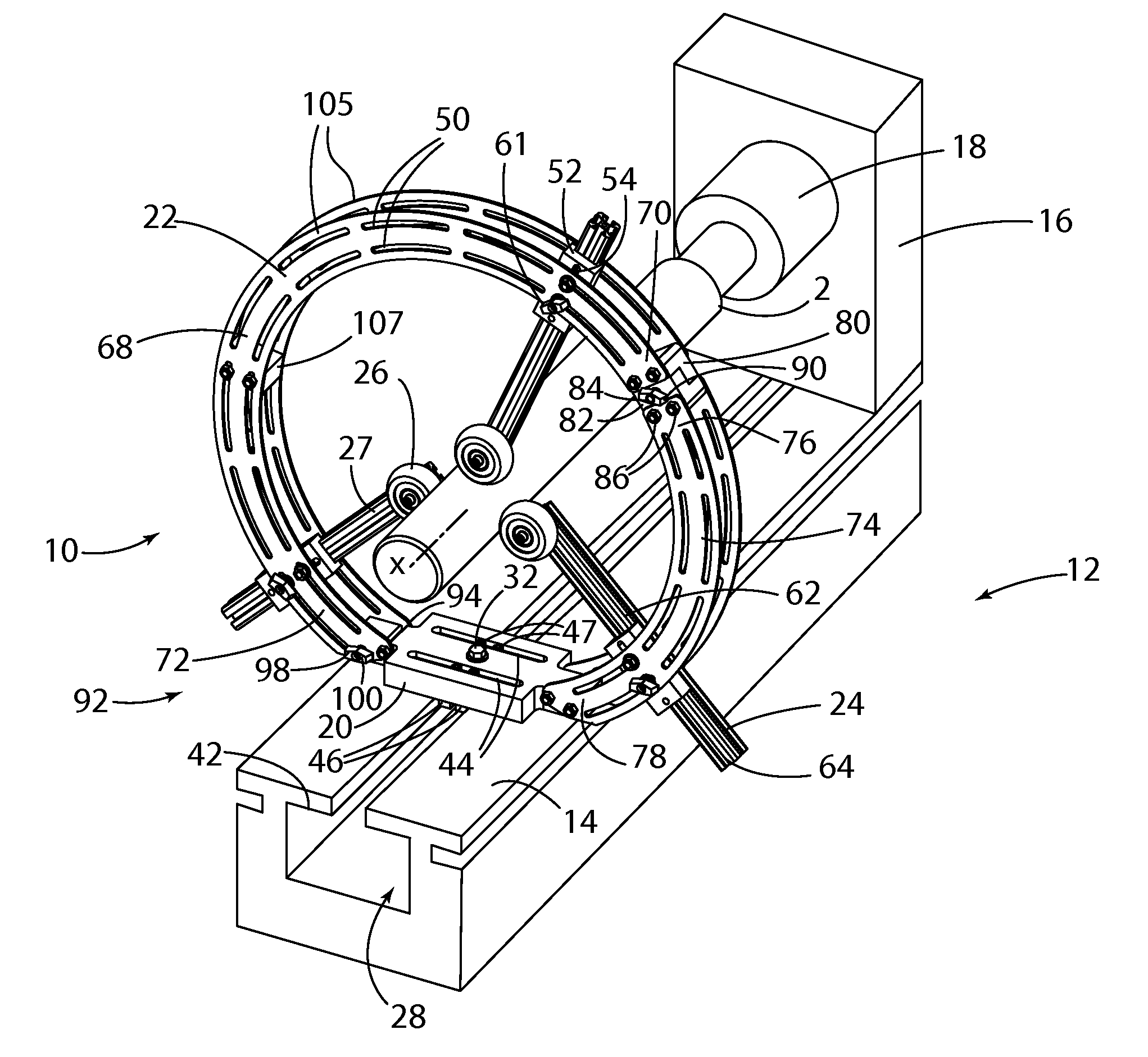
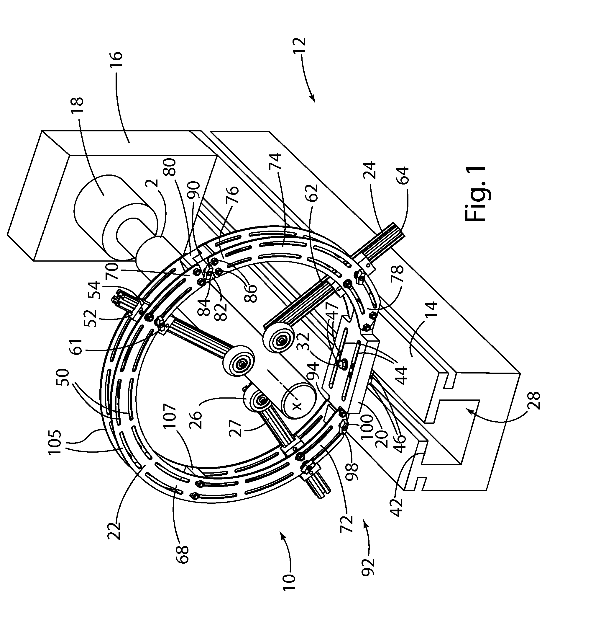
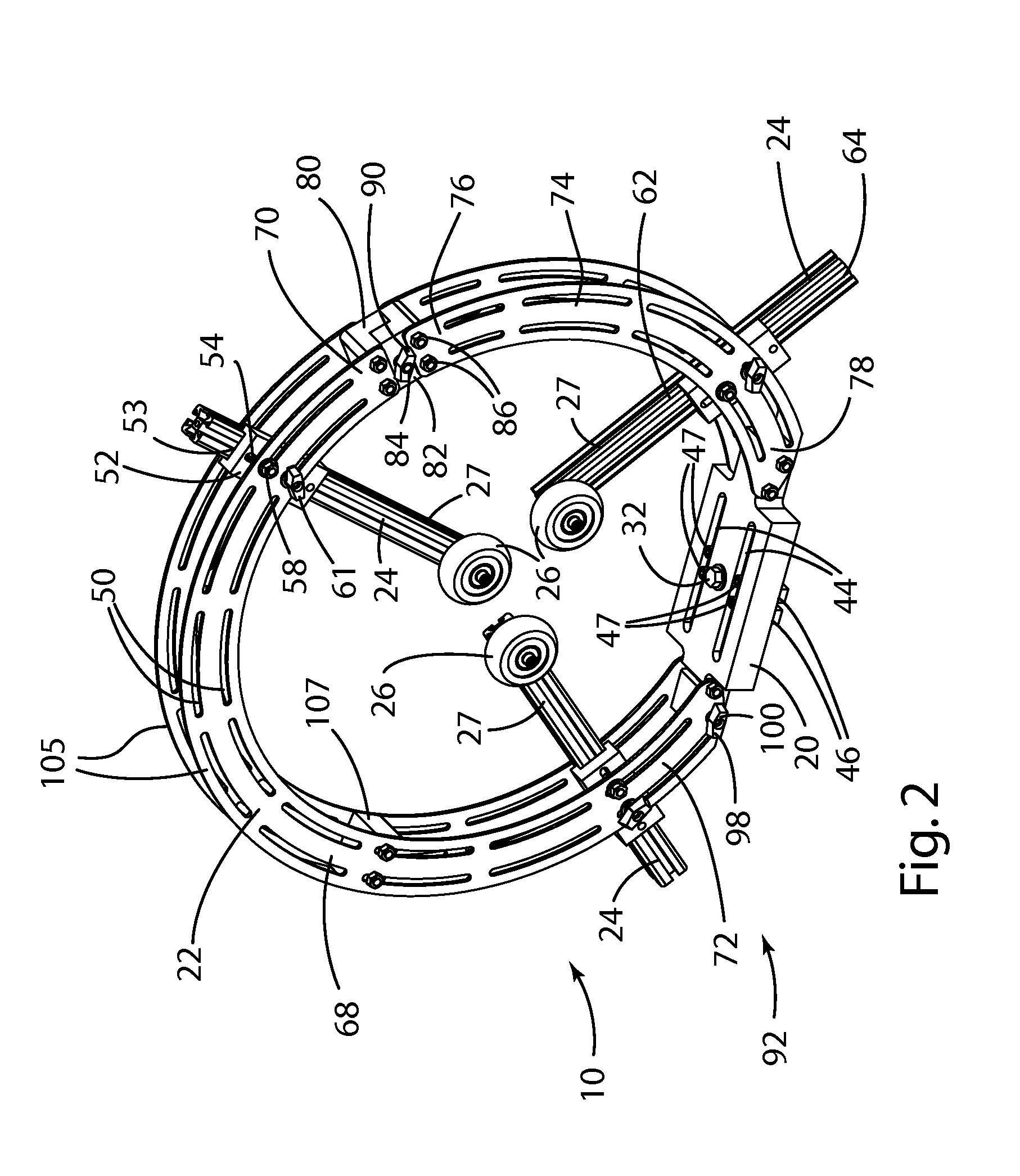
[0046]As shown in the Figures, the present invention relates to a work piece support rest 10 for turning a work piece 2 on a rotating lathe 12 having a lathe bed 14, headstock 16, and headstock sp...


PUM

PropertyMeasurementUnit
Angleaaaaaaaaaa
Lengthaaaaaaaaaa
Widthaaaaaaaaaa

Abstract

A work piece support rest is provided for turning a work piece on a rotating lathe having a lathe bed, headstock, and a headstock spindle, where the work piece is attached to the headstock spindle. The support rest includes an adjustable base releasably attached to the slotted way of the bed via a locking plate and a pair of laterally adjustable way spacers moveable within a laterally extending slot that engage each side of the slotted way. A multi-piece outer ring is releasably attached to the adjustable base. A plurality of roller slides are releasably and adjustably attached to the outer ring, such that each of the roller slides extends radially inwardly and has a roller disposed at an inward distal end thereof for supporting the work piece.

Description

CROSS REFERENCE TO RELATED APPLICATION[0001]The present application claims the benefit under 35 U.S.C. §119(e) of provisional Application No. 61 / 715,481, filed Oct. 18, 2012, entitled “LATHE WORK PIECE SUPPORT TOOL,” the entire contents of which are incorporated herein by reference.FIELD OF THE INVENTION[0002]The present invention generally relates to a work piece support tool for lathes and, more particularly, to an adjustable and adaptable circular work piece support tool that is mountable to multiple lathe configurations.BACKGROUND OF THE INVENTION[0003]Turning lathes, particularly for wooden work pieces, have long been used for creating solid and hollowed forms, such as dowels, rungs, bowls, and vases. Generally, a wooden work piece is secured to a motorized lathe and a handheld cutting tool is used to cut away wood from outside and / or inside the work piece to form the outer and / or inner walls of the shaped form. It is common for a work piece support rest to be placed under or a...

Claims


Application Information

Patent Timeline
IPC IPC(8): B23Q1/76B23B25/00
CPCB23B25/00B23Q1/76B27C7/04B23B23/00B23B2260/004B23B2260/016B23B2260/134B23Q2210/006Y10T82/2572Y10T82/2593
Inventor PEREZ, LELAND T.FOLKERT, JEFFERY S.
Owner CARTER PRODS
Learn More