
Projector, and black level area setting method for projector

a projector and level setting technology, applied in projectors, color television details, instruments, etc., can solve the problems of increasing the cost of the device accordingly, not being able to resolve the black floating, etc., and achieve the effect of saving trouble and reducing the operation time for the position adjustment of the guid

Active Publication Date: 2014-04-17
SEIKO EPSON CORP
View PDF7 Cites 9 Cited by
  • Summary
  • Abstract
  • Description
  • Claims
  • Application Information

AI Technical Summary

Benefits of technology

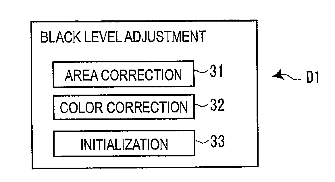
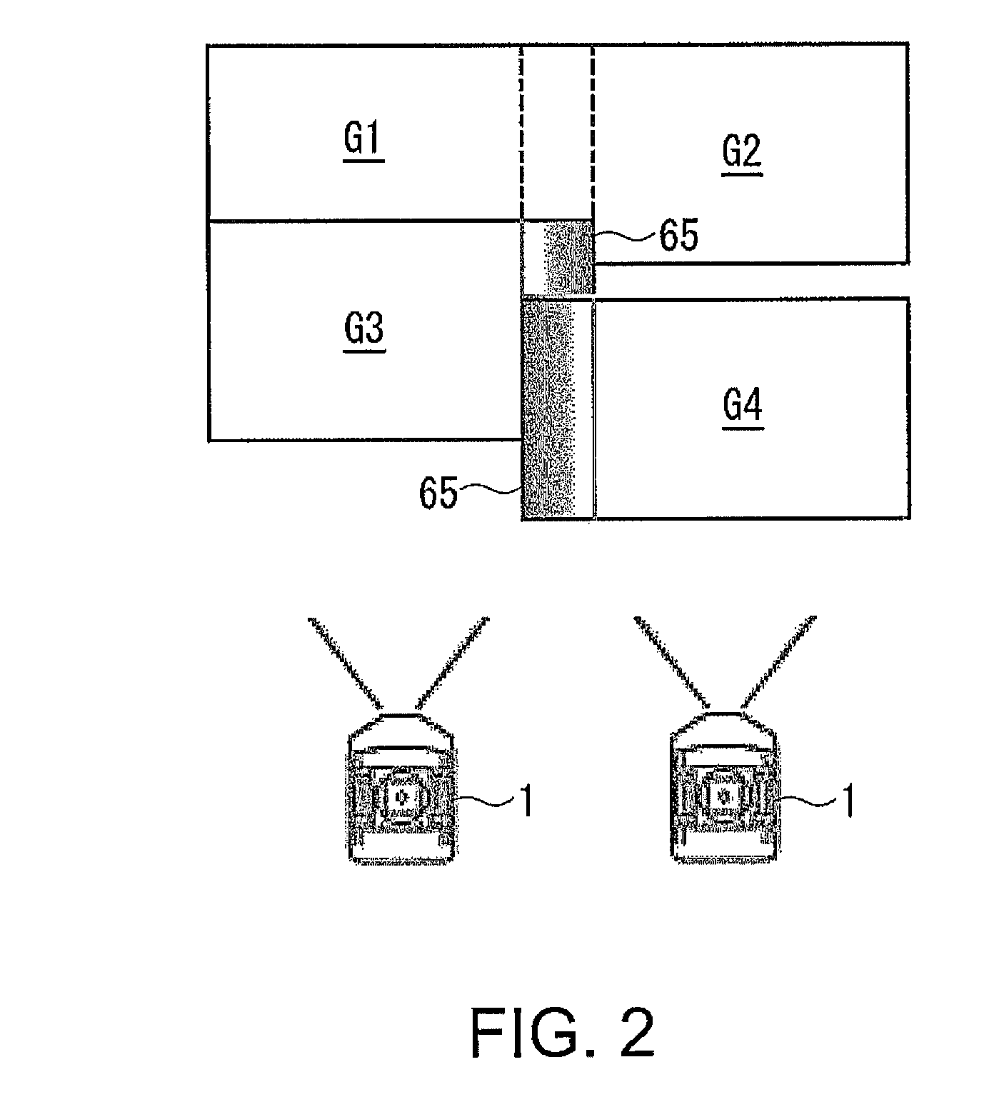
The invention is a device for setting a black level area on a projection image without using a camera or complicated calculations. The device includes a guide for position adjustment, which can be easily adjusted to match the boundary between an overlapping area and a non-overlapping area. The guide is placed on the projection image, allowing for accurate and easy adjustment. The device also includes a blending process to create a seamless transition between overlapping and non-overlapping areas. Additionally, the device can adjust the number of guides based on the geometric correction being performed, making it easier to set the appropriate black level area for the projection surface. The configuration also reduces the time required for position adjustment of the guides by extending the guide line to the frame of the device. Overall, the invention simplifies the process of setting the black level area on a projection image.

Problems solved by technology

However, using of the camera incurs rise in cost of the device accordingly.
Therefore, there is a problem that in the case in which a geometric correction is performed, it is not achievable to set the black level area with respect to the entire light modulation device, and thus, it is not achievable to resolve the black floating due to the leakage light in a non-image forming area where no image is formed.

Method used


Image

  • Projector, and black level area setting method for projector
  • Projector, and black level area setting method for projector
  • Projector, and black level area setting method for projector

Examples


Embodiment Construction

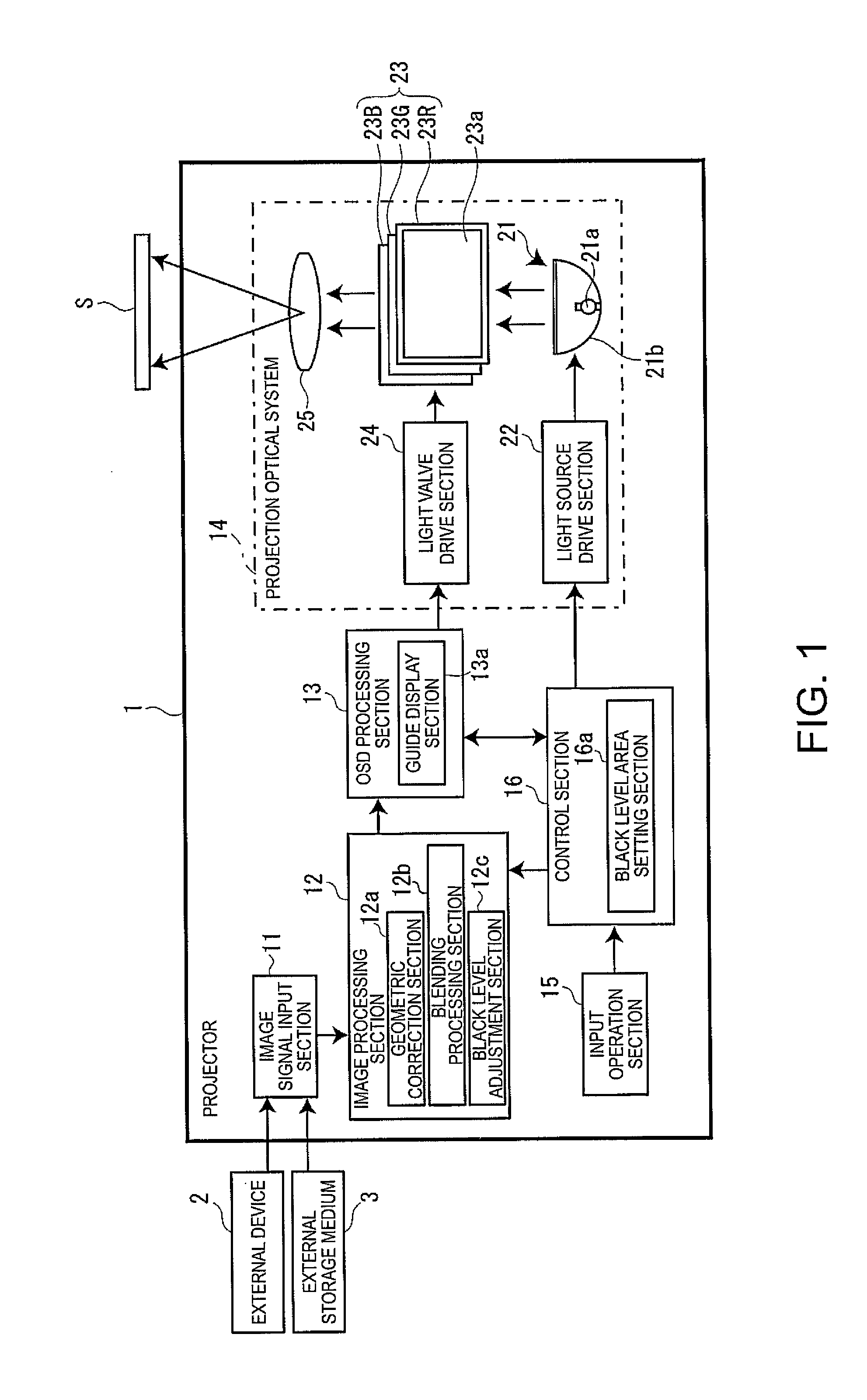
[0037]Hereinafter, an embodiment of the invention will be described with reference to the accompanying drawings. FIG. 1 is a block diagram showing a configuration of a projector 1. As shown in the drawing, the projector 1 is provided with an image signal input section 11, an image processing section 12, an OSD processing section 13, a projection optical system 14, an input operation section 15, and a control section 16 for controlling these sections.

[0038]The image signal input section 11 gets an image signal from an external device 2 such as a personal computer or a DVD player, or an external storage medium 3 such as a USB memory or a compact flash (a registered trade mark) memory card.

[0039]The image processing section 12 performs a predetermined image processing on the image signal, which is gotten by the image signal input section 11, based on an image processing program stored previously. In particular in the present embodiment, the image processing section 12 functions as a ge...


PUM


Abstract

A projector includes a projection optical system adapted to project an image modulated by a light modulation device on a projection surface, a guide display section adapted to dispose a plurality of guides used for setting a black level area, which is an adjustment target area of a black level, on the projection image, and then displays the guides in the case in which projection is performed on the projection surface so that the projection images from a plurality of projectors including the present projector partially overlap each other, an input operation section adapted to receive a position adjustment operation of each of the guides, and a black level area setting section adapted to set the black level area, which is the adjustment target area of the black level, based on an arrangement of the guides.

Description

CROSS-REFERENCE[0001]The entire disclosure of Japanese Patent Application No. 2012-227478, filed Oct. 12, 2012, is expressly incorporated by reference herein.BACKGROUND[0002]1. Technical Field[0003]The present invention relates to a projector capable of a black level adjustment for adjusting a black level of a non-overlapping portion in order to resolve the black floating (lightening of black) due to leakage light in the case in which projection images from a plurality of projectors are projected on a projection surface so as to partially overlap each other, and a black level area setting method for the projector.[0004]2. Related Art[0005]As the projector of this kind, there has been proposed one disclosed in JP-A-2009-5044 (e.g., paragraphs through [0083]; Document 1). In Document 1, the projection image is shot by a camera, and then the black level area to be a black level adjustment target area is specified based on the shooting result.[0006]However, using of the camera incurs ri...

Claims


Application Information

Patent Timeline
IPC IPC(8): G03B21/26G03B21/14
CPCG03B21/147G03B21/26G03B21/13H04N9/3147H04N9/3182H04N9/3185H04N9/3197
Inventor YOSHIMURA, JUN
Owner SEIKO EPSON CORP
Learn More