
Security tag for application to footwear

a technology for security tags and footwear, applied in the field of security tags, can solve the problems of high-end retailers and customers who dislike expensive merchandise damaged by retail theft deterrent devices, shoes are particularly difficult to protect, and articles incur some damag

Active Publication Date: 2014-04-17
SENSORMATIC ELECTRONICS CORP
View PDF1 Cites 8 Cited by
  • Summary
  • Abstract
  • Description
  • Claims
  • Application Information

AI Technical Summary

Benefits of technology

The patent claim is that the described features, advantages, and characteristics of the invention can be combined in different ways in different embodiments. This allows for flexibility and customization in the practice of the invention.

Problems solved by technology

In the non-packaged good scenario, the article incurs some damage as a result from the pins insertion therethrough.
High-end retailers and customers dislike having expensive merchandise (e.g., leather goods) damaged by retail theft deterrent devices.
Shoes are especially difficult to protect using devices having pins, as the materials from which the shoes are constructed often suffer permanent damage from the pins.
Shoes present other difficulties for pinned security tags.
For example, the materials from which certain shoes are made are often too rigid to insert the pins therein and / or too thick to insert the pins therethrough such that the pins can be locked by the locking mechanisms.
This practice is fine for a few shoe types (e.g., sneakers), but the security tags interfere with the fitting and lacing process of the shoes.
One can appreciate that such pinching and clamping applies a compressive force on the article, which may cause damage to the article.
Also, if a pinching or clamping force is not provided for securing the pinless security tag to the article, then the security tag can be removed from the article by an unauthorized person.
As such, the security tag may not actually prevent the unauthorized removal of the article from the retail store.

Method used


Image

  • Security tag for application to footwear
  • Security tag for application to footwear
  • Security tag for application to footwear

Examples


Embodiment Construction

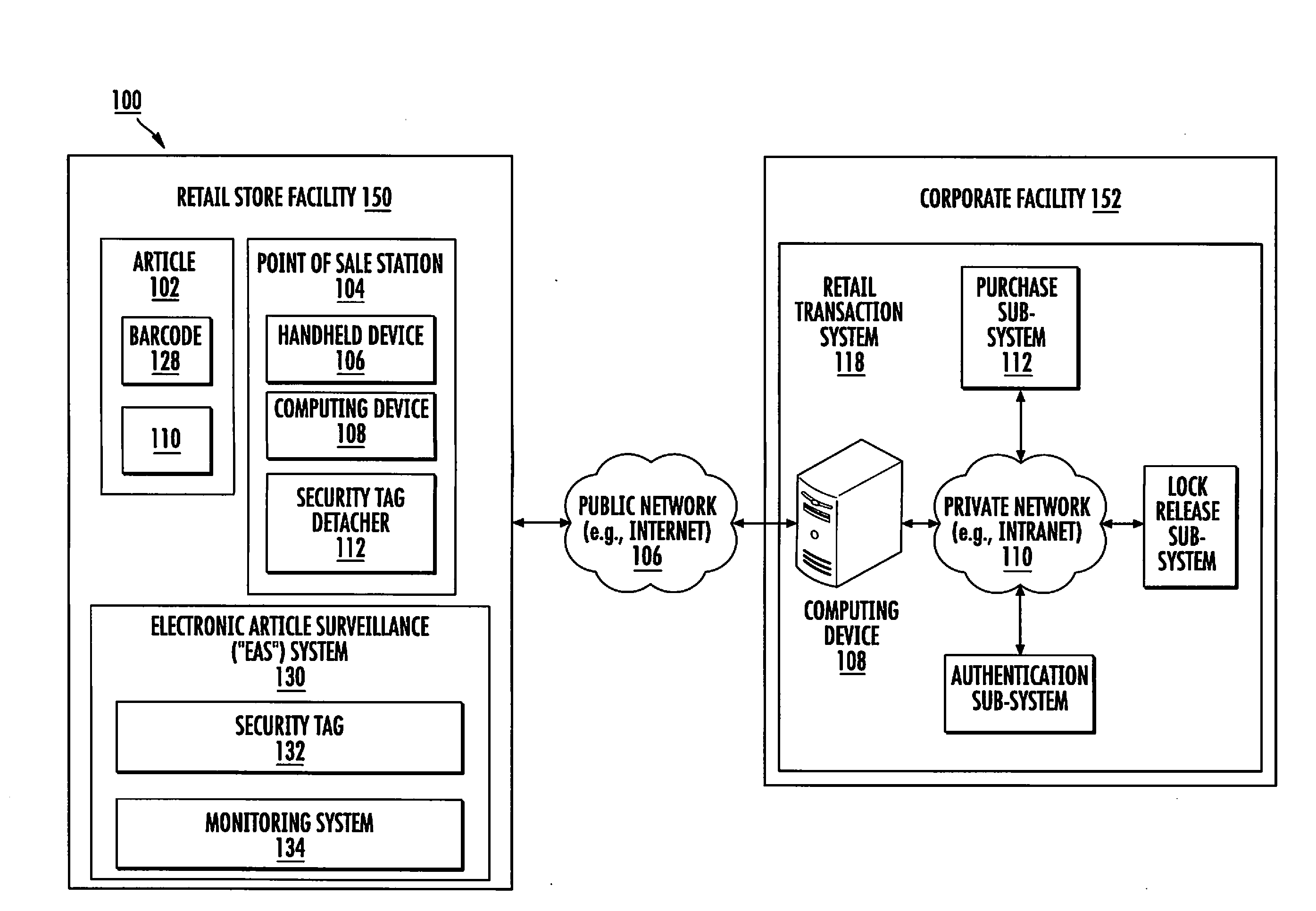
[0025]It will be readily understood that the components of the embodiments as generally described herein and illustrated in the appended figures could be arranged and designed in a wide variety of different configurations. Thus, the following more detailed description of various embodiments, as represented in the figures, is not intended to limit the scope of the present disclosure, but is merely representative of various embodiments. While the various aspects of the embodiments are presented in drawings, the drawings are not necessarily drawn to scale unless specifically indicated.

[0026]The present invention may be embodied in other specific forms without departing from its spirit or essential characteristics. The described embodiments are to be considered in all respects as illustrative. The scope of the invention is, therefore, indicated by the appended claims. All changes which come within the meaning and range of equivalency of the claims are to be embraced within their scope.

[...


PUM


Abstract

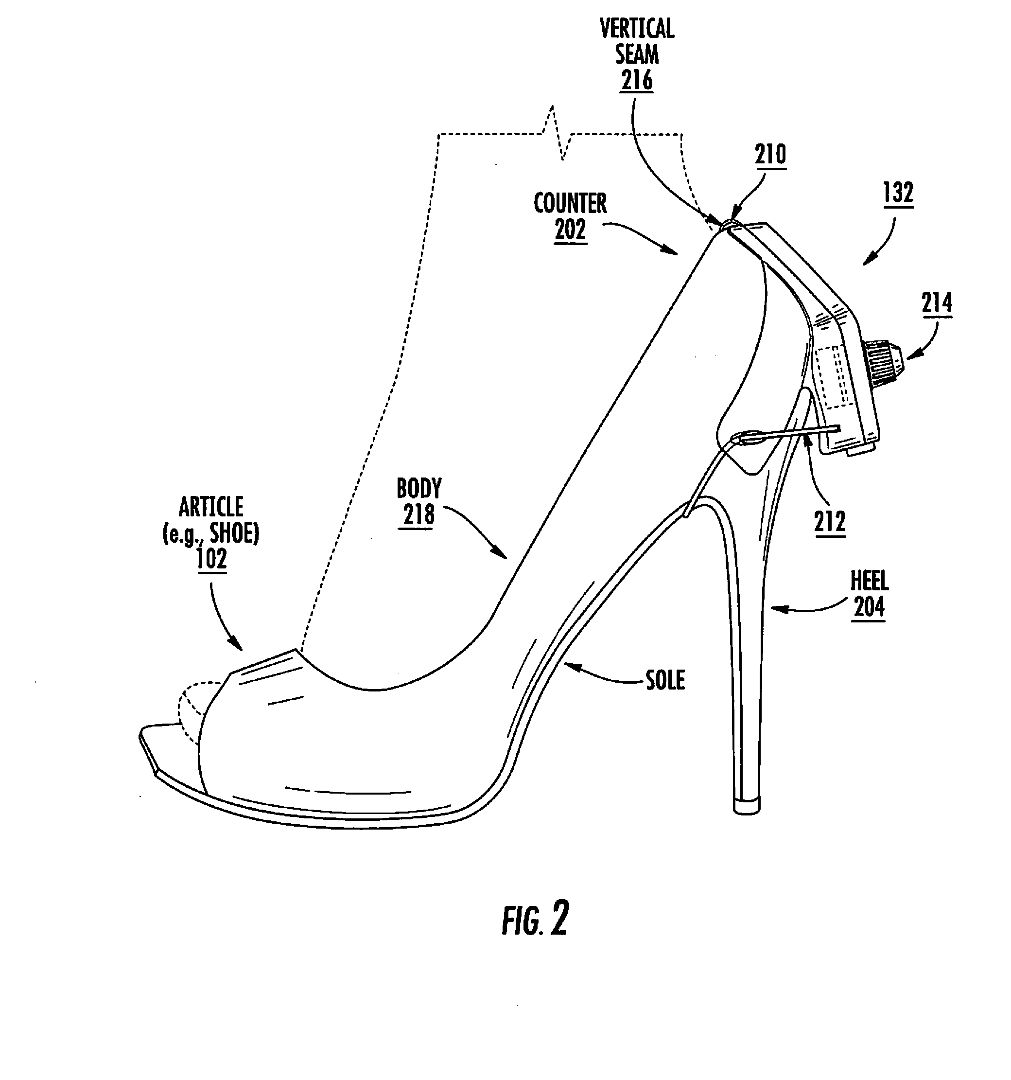
Systems (100) and methods (1500) for operating a security tag (132) of an Electronic Article Surveillance (“EAS”) system. The methods involving: attaching a clip (210) to a curved sidewall (202) of an article (102) such that a central body (304) of the security tag is vertically aligned with a central axis of the curved sidewall; maintaining the vertical alignment by locating first and second flanges (306, 502) of the security tag against respective opposing surface areas of the curved sidewall; wrapping a securement member (212) of the security tag around an elongate structure (204) of the article which is offset from the curved sidewall in at least one direction and which protrudes away from a main body (218) of the article; and locking the securement member in a position wrapped around the elongate structure of the article using a mechanical locking mechanism (214) of the security tag.

Description

CROSS REFERENCE TO RELATED APPLICATIONS[0001]This application is a non-provisional application of U.S. Provisional Application No. 61 / 691,535 filed on Aug. 21, 2012, which is herein incorporated in its entirety.STATEMENT OF THE TECHNICAL FIELD[0002]The inventive arrangements relate to security tags used in Electronic Article Surveillance (“EAS”) systems. More particularly, the inventive arrangements concern security tags and methods for preventing the unauthorized removal of articles (e.g., footwear) from a given location (e.g., a retail store).DESCRIPTION OF THE RELATED ART[0003]A typical EAS system in a retail setting may comprise a monitoring system and at least one security tag or label attached to an article to be protected from unauthorized removal. The monitoring system establishes a surveillance zone in which the presence of security tags and / or labels can be detected. The surveillance zone is usually established at an access point for the controlled area (e.g., adjacent to ...

Claims


Application Information

Patent Timeline
Patent Type & Authority Applications(United States)
IPC IPC(8): G08B13/24
CPCG08B13/2434E05B73/0029G08B13/149E05B45/005E05B73/0017G08B13/1445G08B21/24
Inventor LUO, DANHUIFORD, JOHN C.FORD, KALEYNGUYEN, THANG TATTURGEON, CHARLES T.
Owner SENSORMATIC ELECTRONICS CORP
Learn More