Device for cooling a component of an electrical machine using cooling coils

a technology of cooling coils and components, which is applied in the direction of dynamo-electric machines, magnetic circuit shapes/forms/construction, supports/enclosements/casings, etc., can solve the problems of limited choice of coolant and localized leakage points in the coolant circuit, and achieve no risk of thermally-induced power loss or failure of the motor. , the effect of high power capability

Inactive Publication Date: 2014-04-17
SIEMENS AG
View PDF23 Cites 1 Cited by
  • Summary
  • Abstract
  • Description
  • Claims
  • Application Information

AI Technical Summary

Benefits of technology

[0020]A device in accordance with the present invention for cooling can be especially suitable for use in a dynamoelectric machine, especially a torque motor or a linear motor having a rotor and / or a stator. An electric motor or a generator, especially designed as a torque motor, is characterized by laminated cores having a plurality of windings. If these motors provide a high power capability a cooling of these laminated cores both in the stator but also in the rotor is provided to a great extent so that there is no risk of thermally-induced power losses or failures of the motor. Even cooling demands special attention here, which is why this device, as already stated, is especially well suited.

Problems solved by technology

In addition the necessity might arise for connecting hoses within the electrical machine, which restricts the choice of coolant.
Furthermore leakage points in the coolant circuit are often localized at connections and hose couplings.

Method used


Image

  • Device for cooling a component of an electrical machine using cooling coils
  • Device for cooling a component of an electrical machine using cooling coils
  • Device for cooling a component of an electrical machine using cooling coils

Examples


Embodiment Construction

[0025]Throughout all the figures, same or corresponding elements may generally be indicated by same reference numerals. These depicted embodiments are to be understood as illustrative of the invention and not as limiting in any way. It should also be understood that the figures are not necessarily to scale and that the embodiments are sometimes illustrated by graphic symbols, phantom lines, diagrammatic representations and fragmentary views. In certain instances, details which are not necessary for an understanding of the present invention or which render other details difficult to perceive may have been omitted.

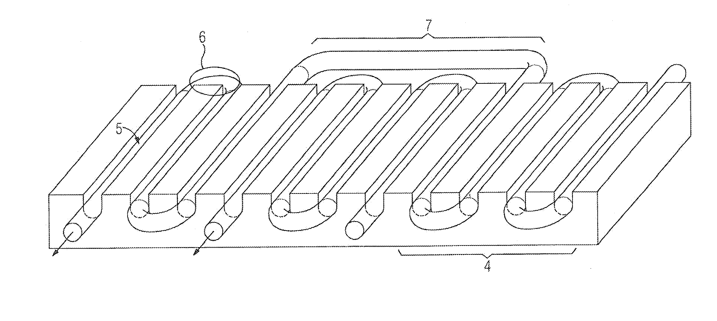
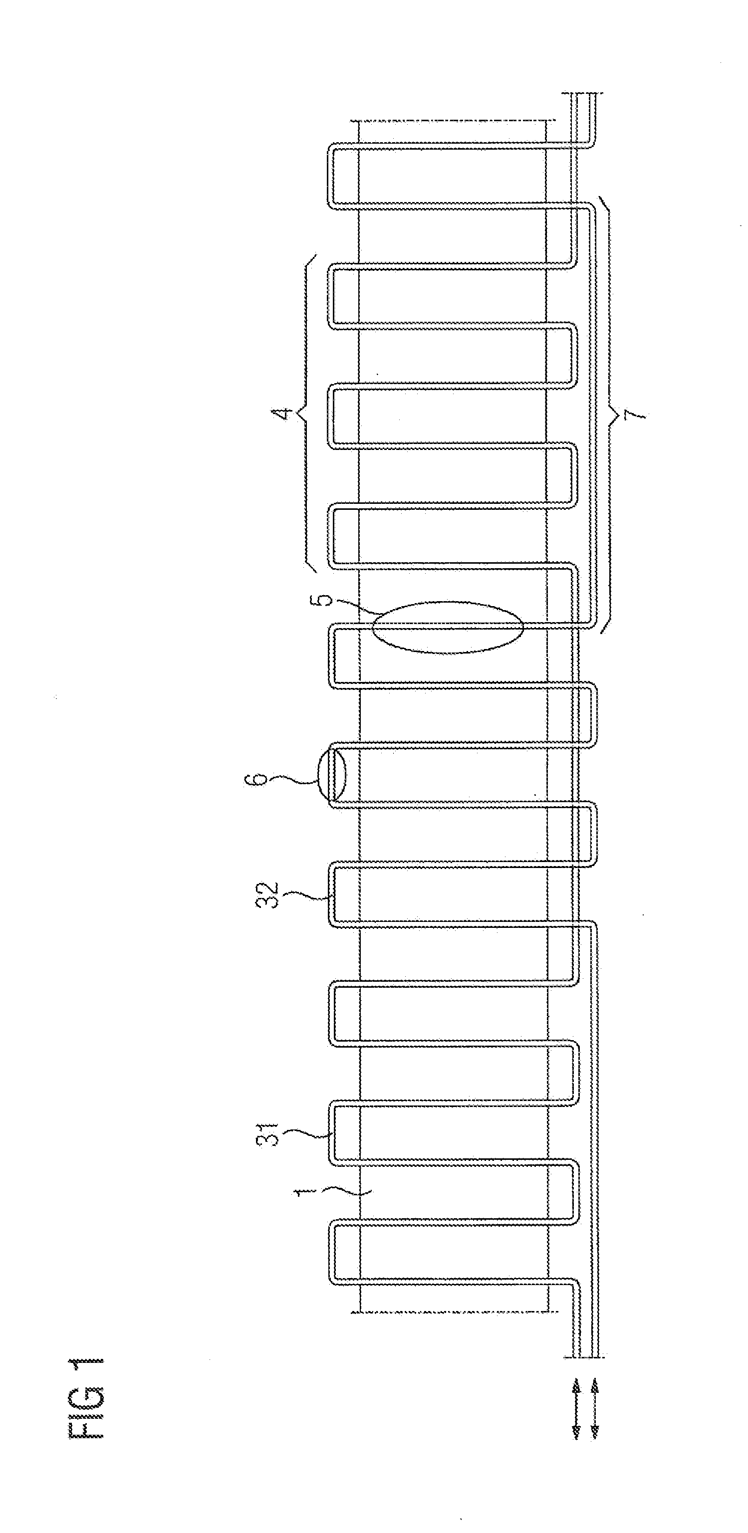
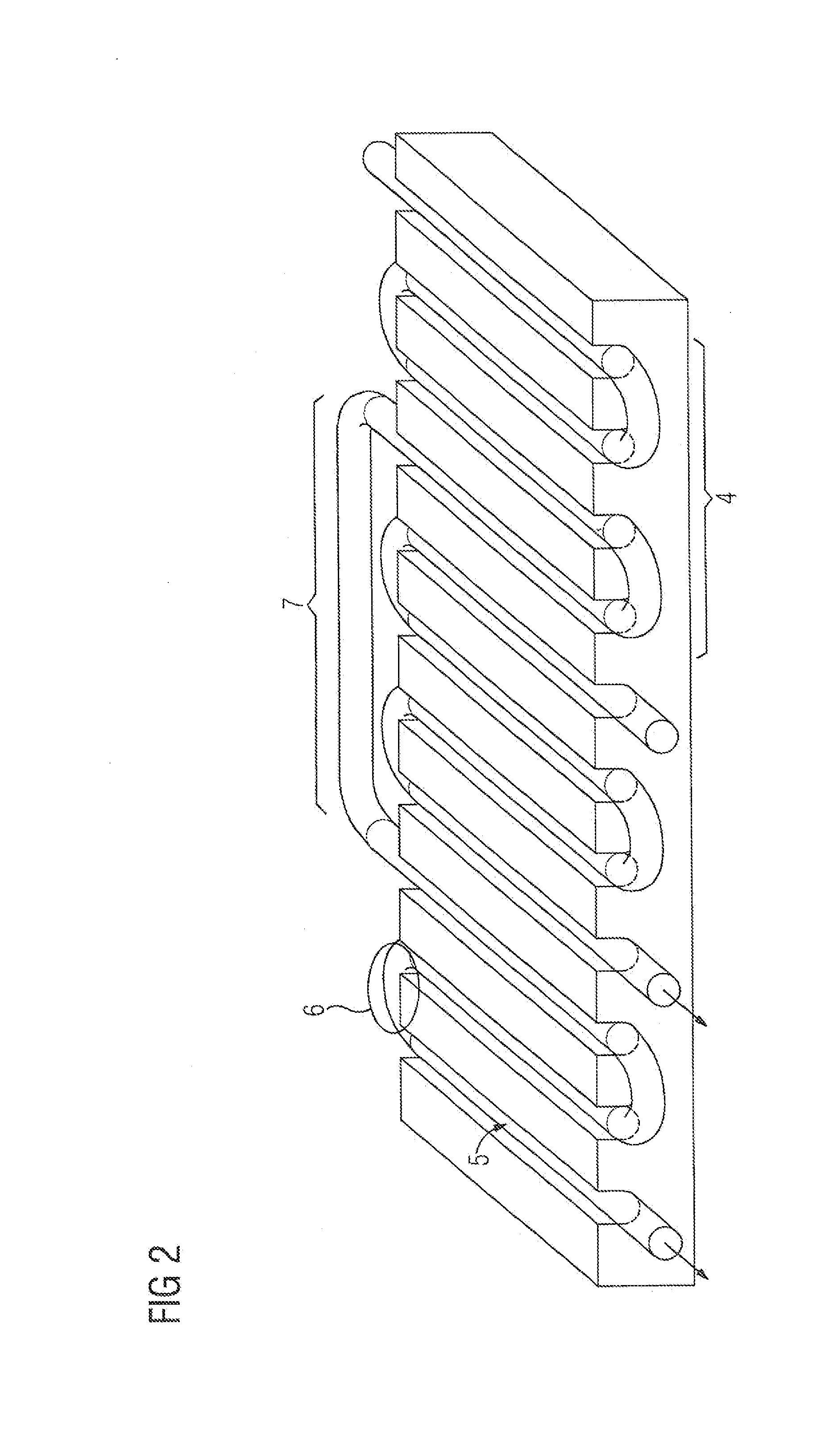
[0026]Turning now to the drawing, and in particular to FIG. 1, there is shown a schematic and simplified illustration of a possible course of cooling loops in a component 1 in which cooling coils 31, 32 are held. The cooling coils 31, 32 pass in some areas in a serpentine shape through the component 1. The cooling coils 31, 32 include serpentine-shaped sections 4, as well as...


PUM


Abstract

A device for cooling a component includes first and second cooling cons for circulation of a coolant. The first and second cooling coils have serpentine sections and distance sections connecting neighboring ones of the serpentine sections to each other for cooling individual non-neighboring component areas. Each distance section is configured to bridge a component area which is cooled by a one of the serpentine-shaped sections of the first and second cooling coils.

Description

CROSS-REFERENCES TO RELATED APPLICATIONS[0001]This application claims the priority of European Patent Application, Serial No. 121 88 383, filed Dec. 12, 2012, pursuant to 35 U.S.C. 119(a)-(d), the disclosure of which is incorporated herein by reference in its entirety as if fully set forth herein.BACKGROUND OF THE INVENTION[0002]The present invention relates to the field of cooling a component of an electrical machine using a number of cooling coils[0003]The following discussion of related art is provided to assist the reader in understanding the advantages of the invention, and is not to be construed as an admission that this related art is prior art to this invention.[0004]Windings through which current flows in laminated cores, such as are used in dynamoelectric machines for example, often heat up the laminated core into which they are inserted, through eddy currents for example, to a significant extent. Therefore sufficient cooling is necessary, especially for electrical machine...

Claims


Application Information

Patent Timeline
Patent Type & Authority Applications(United States)
IPC IPC(8): H02K1/20
CPCH02K1/20H02K9/19H02K5/20
Inventor GADELMEIER, MICHAEL-ADOLFLEFRANK, HEINRICH
Owner SIEMENS AG
Why Eureka
Try Eureka