Casing brake assembly
a brake assembly and casing technology, applied in the field of casing brake assembly, can solve the problems of requiring additional effort in their construction and additional space at the installation site, and achieve the effects of improving the sealing between the braking and sealing element and the filling tube, facilitating the attachment of the free end, and uniform braking force and/or sealing
- Summary
- Abstract
- Description
- Claims
- Application Information
AI Technical Summary
Benefits of technology
Problems solved by technology
Method used
Image
Examples
first embodiment
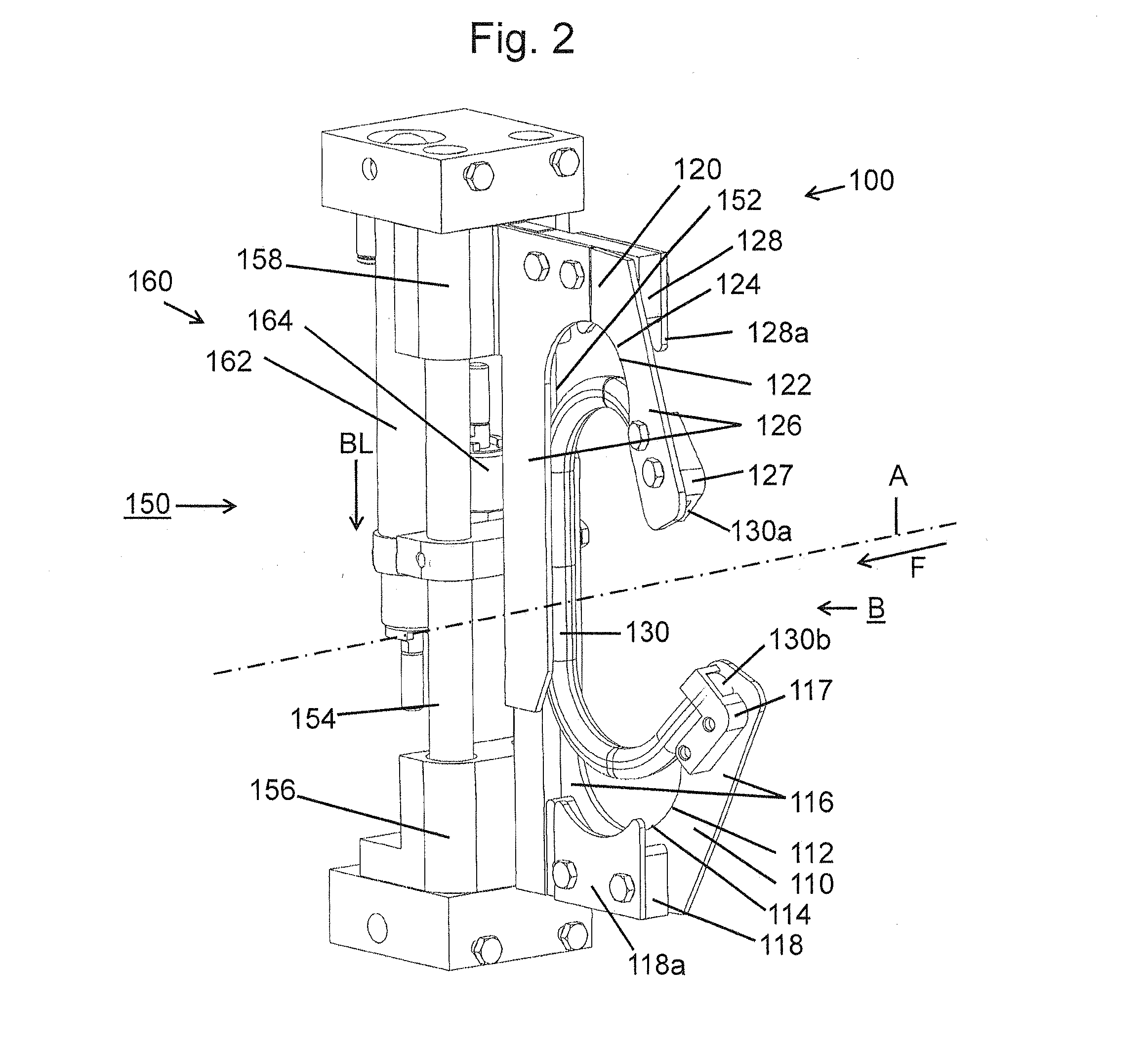
[0052]FIG. 2 is a schematic and perspective view to the casing brake assembly 100 according to the present invention.
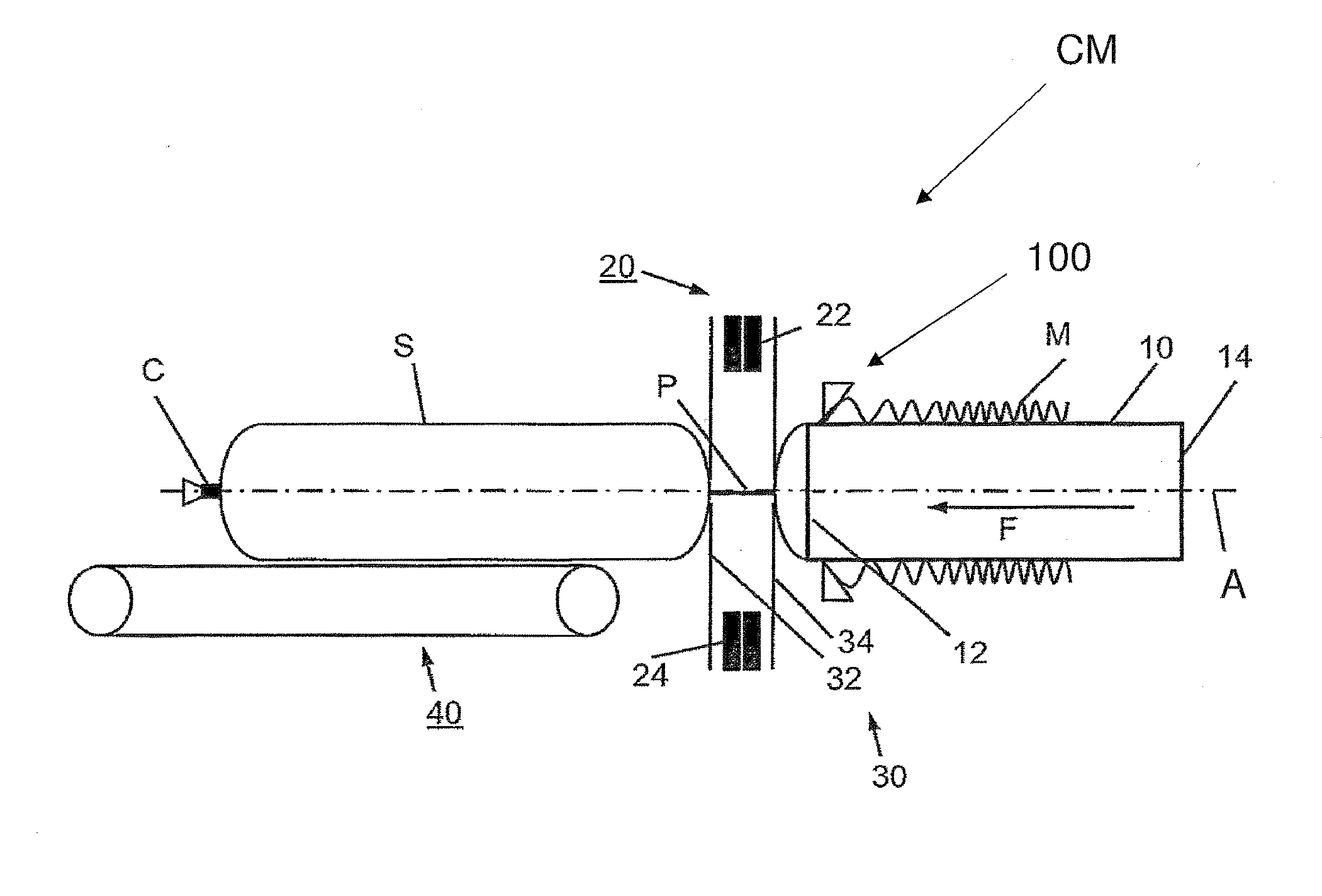
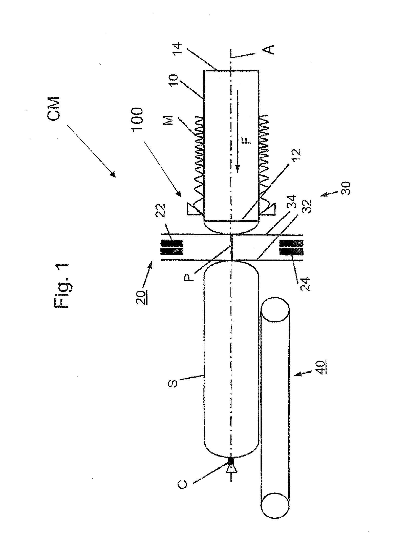
[0053]Casing brake assembly 100 according to FIG. 2 comprises two support elements, a lower support element 110 and an upper support element 120 which are positioned diametrically below and above filling tube 10 (not shown in FIG. 2). Upper and lower support elements 110, 120 are formed by at least approximately vertically arranged plates which comprise approximately U-shaped cutouts 112, 122. Cutouts 112, 122 face towards filling tube 10. Support elements 110, 120 include approximately semicircular bottom portions 114, 124 and approximately vertically aligned leg-portions 116, 126. As it can be seen in FIG. 2, lower and upper support elements 110, 120 are arranged vertically and with a small axial distance in feeding direction F.
[0054]Casing brake assembly 100 comprises a braking and sealing body B in the form of a single string-shaped braking and sealing element 130...
second embodiment
[0068]FIG. 4 is a schematic and perspective view to the casing brake assembly 200 according to the present invention.
[0069]Casing brake assembly 200 according to FIG. 4 comprises a lower support element 210 and an upper support element 220 which are positioned diametrically below and above filling tube 10. Upper and lower support elements 210, 220 are formed by at least approximately vertically arranged plates which comprise approximately U-shaped cutouts 212, 222. Cutouts 212, 222 are directed towards filling tube 10. Support elements 210, 220 include approximately semicircular bottom portions 214, 224 and leg portions 216, 226.
[0070]Braking and sealing body B of casing brake 200 is formed by two braking and sealing elements 230, 240. First braking and sealing element 230 is mounted to bottom portion 214 matching cutout 212 of lower support element 210, and second braking and sealing element 240 is mounted to bottom portion 224 matching cutout 222 of upper support element 220. Firs...
third embodiment
[0079]FIG. 6 is a schematic and perspective view to a casing brake assembly 300 according to the present invention.
[0080]Casing brake assembly 300 according to FIG. 6 comprises a first or lower support element 310 and a second or upper support element 320 which are positioned diametrically below and above filling tube 10. Upper and lower support elements 310, 320 are formed by at least approximately vertically arranged plates which comprise approximately U-shaped cutouts 312, 322. Cutouts 312, 322 are directed or face towards filling tube 10. Support elements 310, 320 include an approximately semicircular bottom portion 314, 324 and leg portions 316, 326.
[0081]Casing brake assembly 300 comprises a brake body B including a first braking and sealing element 330 and a second braking and sealing element 340. First braking and sealing element 330 is mounted to cutout 314 of lower support element 310, and second braking and sealing element 340 is mounted to cutout 324 of upper support ele...
PUM
| Property | Measurement | Unit |
|---|---|---|
| frictional force | aaaaa | aaaaa |
| brake force | aaaaa | aaaaa |
| pressure | aaaaa | aaaaa |
Abstract
Description
Claims
Application Information
 - R&D
- Intellectual Property
- Life Sciences
- Materials
- Tech Scout
- Unparalleled Data Quality
- Higher Quality Content
- 60% Fewer Hallucinations
Browse by: Latest US Patents, China's latest patents, Technical Efficacy Thesaurus, Application Domain, Technology Topic, Popular Technical Reports.
© 2025 PatSnap. All rights reserved.Legal|Privacy policy|Modern Slavery Act Transparency Statement|Sitemap|About US| Contact US: help@patsnap.com


