
Laminated LED array and/or products including the same

a technology of led arrays and led lights, applied in the direction of fixed installation, lighting and heating equipment, lighting support devices, etc., can solve the problems of providing cost-effective techniques and still exist challenges, and achieve the effect of improving luminous efficacy and cost-effectiveness

Inactive Publication Date: 2014-04-10
GUARDIAN GLASS LLC
View PDF22 Cites 56 Cited by
  • Summary
  • Abstract
  • Description
  • Claims
  • Application Information

AI Technical Summary

Benefits of technology

The patent text describes the need for improved LED-inclusive devices that can be used in various applications. The technical effects of the patent include providing LED-inclusive subassemblies that can be easily integrated into different devices, improving luminous efficacy, CRI matching, and lifetimes, as well as managing the accumulation of heat during operation. The patent also describes methods for making the LED-inclusive devices, such as a window for a vehicle and an electronic device. The LED devices are connected to one another via flexible wires and can be individually addressed and powered. An optical out-coupling layer stack is disposed over the LEDs to shape the light output. Overall, the patent aims to provide more flexible and efficient LED-inclusive devices that can be used in various applications.

Problems solved by technology

Furthermore, challenges still exist when it comes to providing cost-effective techniques for integrating the active materials into device packages, interconnecting them into modules, managing the accumulation of heat during their operation, spatially directing and homogenizing their light output at desired levels of chromaticity and intensity, etc.

Method used


Image

  • Laminated LED array and/or products including the same
  • Laminated LED array and/or products including the same
  • Laminated LED array and/or products including the same

Examples


Embodiment Construction

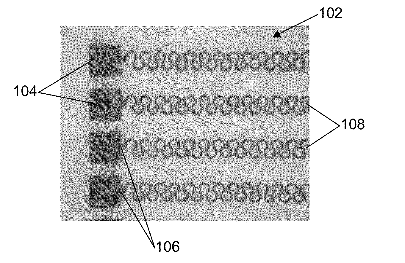
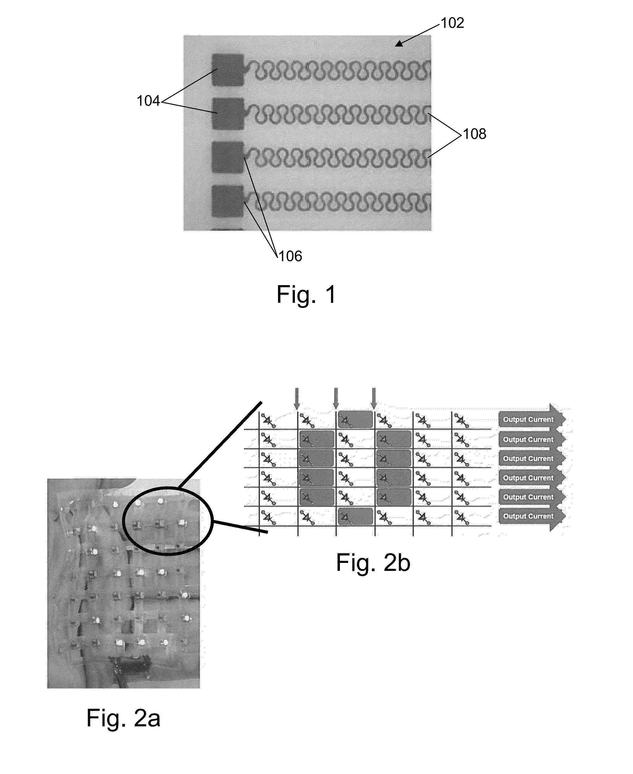
[0022]Certain example embodiments relate to techniques for incorporating LED devices into lighting modules that manage light conversion, extraction and distribution in ways that (i) allow packaging in unique form-factors such as complex multi-axial bends, (ii) reduce adverse effects related to heat build-up during operation, (iii) wavelength convert and improve light out-coupling efficiencies, and / or (iv) distribute light in desirable spatial orientations. This is accomplished in certain example embodiments by decoupling LED devices into its various components including, for example, (i) bare dice, (ii) phosphors, and (iii) optical element arrays and out-coupling scatterers.

[0023]The above-described and / or other problems could be solved, in part, by provided stretchable LED array based circuits that can conform to the shape of a substrate or superstrate and can be readily deformable, while still maintaining their functionality. Such assemblies could be useful in a variety of applica...


PUM

PropertyMeasurementUnit
Angleaaaaaaaaaa
Temperatureaaaaaaaaaa
Diameteraaaaaaaaaa

Abstract

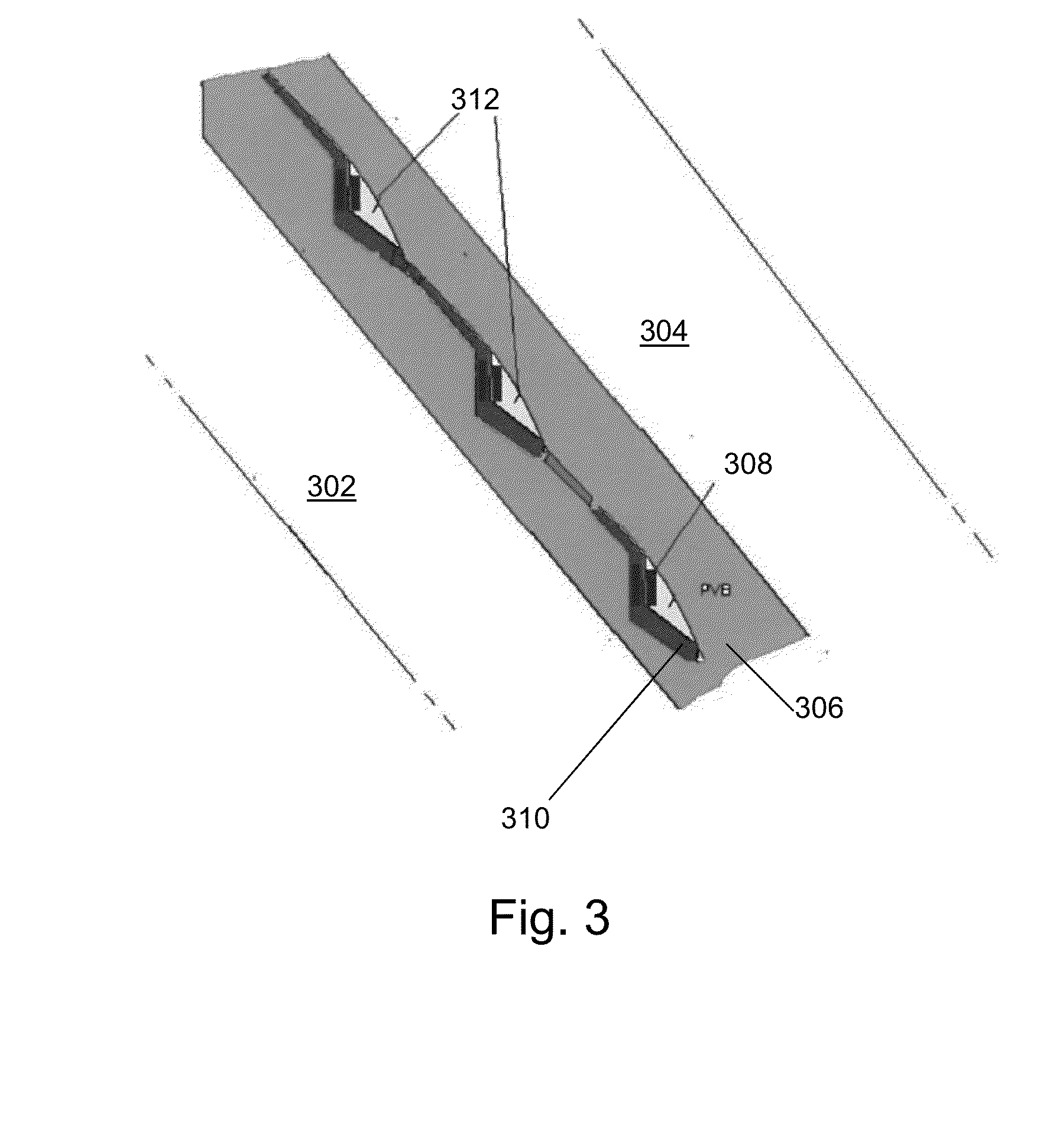
In certain example embodiments, light emitting diodes (LEDs) may be disposed on a deformable and flexible backbone sheet and chained together in an array, e.g., via flexible wiggle wires. Such flexible wiggle wires may also provide an electrical connection to an external power source. An optical out-coupling layer stack (OCLS) system may help serve as an index matching layer, heat sink, étendue conserver, etc. The backbone may be formed to a shape tailored to its ultimate application. Applications may include, for example, automotive (such as Center High Mounted Stop Lamp (CHMSL) applications), lighting, signage, and / or other applications. In an example CHMSL application, the deformable sheet with the LED array thereon has a step, sinusoidal, or other shape matched to the angle and / or curvature of the glass such that the LEDs produce light primarily in a direction parallel to a surface on which a vehicle is located.

Description

[0001]Certain example embodiments relate to light emitting diode (LED) systems, and / or methods of making the same. More particularly, certain example embodiments relate to laminated LED arrays, products including such laminated LED arrays, and / or methods of making the same. In certain example embodiments, LEDs may be disposed on a flexible backbone sheet and chained together in an array. The backbone may be formed to a shape tailored to its ultimate application.BACKGROUND AND SUMMARY OF EXAMPLE EMBODIMENTS OF THE INVENTION[0002]Light emitting diodes (LEDs) have emerged as a technology used in general illumination, display, signage and other applications. There have been some attempts to improve luminous efficacy, CRI matching, and lifetimes, although there remains room for yet further improvements. Furthermore, challenges still exist when it comes to providing cost-effective techniques for integrating the active materials into device packages, interconnecting them into modules, mana...

Claims


Application Information

Patent Timeline
IPC IPC(8): F21V21/16
CPCF21V21/16B32B17/10036B32B17/10541B32B17/10761B32B17/10788B60Q1/302B60Q1/268B60Q1/2696F21S43/19F21S43/14B32B17/10005B32B2379/08F21Y2107/70
Inventor VEERASAMY, VIJAYEN S.
Owner GUARDIAN GLASS LLC
Learn More