Electronic control device
a control device and electronic technology, applied in the direction of electrical apparatus, closed casings, electrical apparatus, etc., can solve the problems of deteriorating and achieve the effect of reducing the positioning shift of the first and second enclosure members and improving the workability of the assembly
- Summary
- Abstract
- Description
- Claims
- Application Information
AI Technical Summary
Benefits of technology
Problems solved by technology
Method used
Image
Examples
embodiment 1
[0071]FIG. 7 is an enlarged schematic view of a part (a circle C) of FIG. 5, for explaining a modification of the
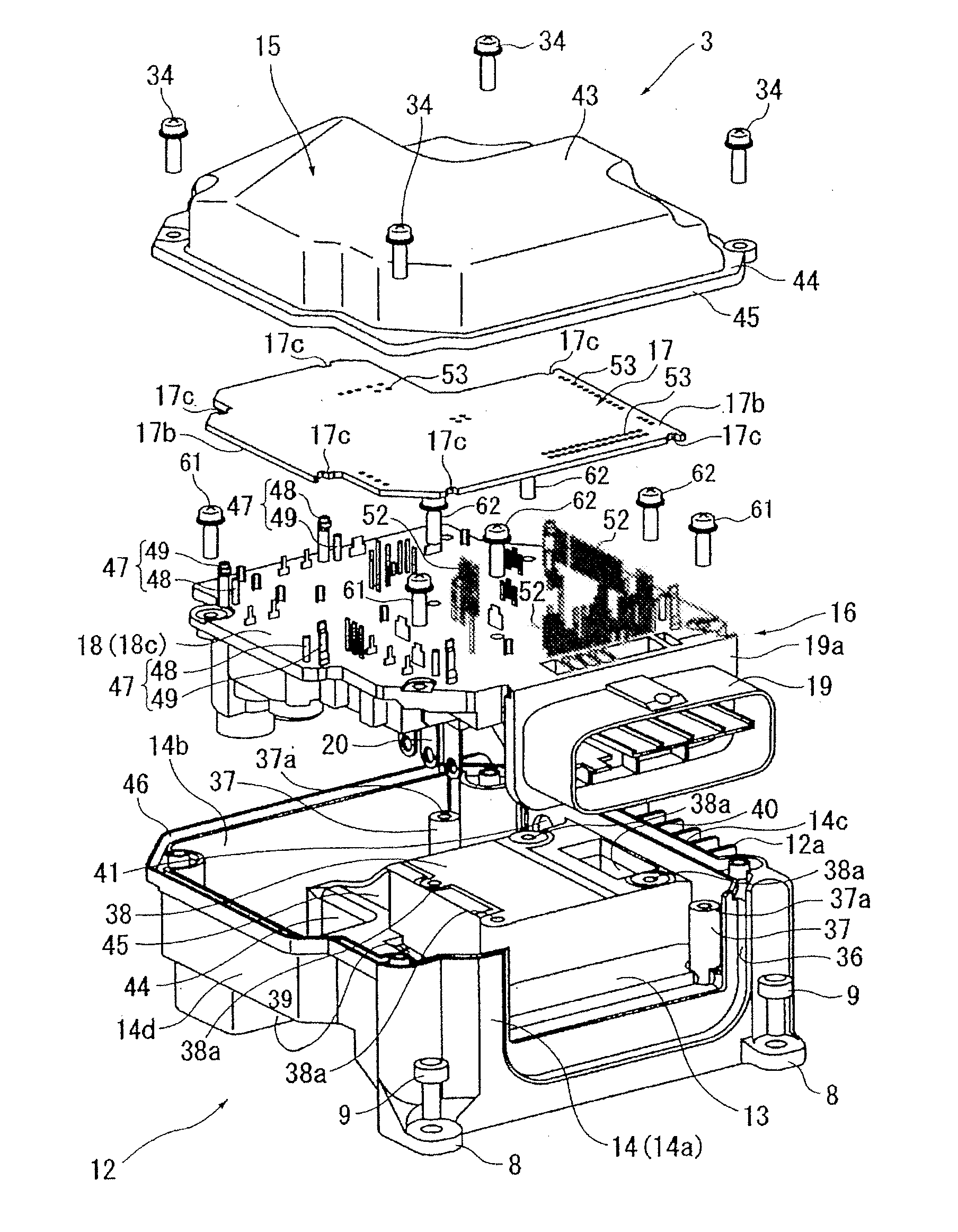
[0072]The protrusion 70 is formed into a substantially pyramidal shape or frustum shape, and has tapered surfaces 73 that tilt or slope in an oblique upward direction from a bottom wall surface 71c side toward an opening 72 side of the seal groove 46.
[0073]By forming such tapered surfaces 73, as compared with the case of the embodiment 1 in which the protrusion 70 whose side surface merely extends from the bottom wall surface side of the inner wall surface toward the opening side of the seal groove is formed (i.e. an angle θ between the bottom wall surface 71c and the protrusion 70 is 90°), in a case where a sealing material such as a liquid gasket is provided around the protrusion 70 in the seal groove 46, an area around the protrusion 70 and a root portion of the protrusion 70 can be easily filled with the sealing material without any void.
[0074]
[0075]FIG. 8 is an enlar...
embodiment 3
[0078]FIG. 9 is an enlarged schematic view for explaining a modification of the
[0079]The protrusion 70 is formed from a pair of protruding portions 75a and 75b that protrude from the bottom wall surface 71c toward the opening 72 of the seal groove 46. The protruding portions 75a and 75b are arranged with a predetermined space (a predetermined width) w1 provided between these protruding portions 75a and 75b. Further, the width w1 between the protruding portions 75a and 75b is set to be greater than the thickness t1 of the protruding edge 45 so that when the protruding edge 45 is inserted into the seal groove 46, a part (a top end) of the protruding edge 45 is fitted between the protruding portions 75a and 75b. With this setting, the protruding edge 45 inserted into the seal groove 46 is sandwiched between the protruding portions 75a and 75b. Therefore, as compared with the embodiment 1, the movement of the protruding edge 45 in the width direction of the seal groove 46 is more limite...
embodiment 5
[0085]FIG. 11 is an enlarged schematic view for explaining a modification of the
[0086]The protrusion 70 is formed by bending a part of the protruding edge 45 of the cover 15 in a direction of the inner circumferential surface 71a (in FIG. 11, the protruding edge 45 is bent from a root portion of the protruding edge 45). Also in this case, as same as the case of the embodiment 5, when the protruding edge 45 is inserted into the seal groove 46, the movement of the protruding edge 45 in the width direction of the seal groove 46 is limited.
[0087]Here, in the case of the embodiment 5, the cover 15 formed by, for instance, aluminium die-casting is used. However, in the case where the protrusion 70 is formed by the bending process as shown in FIG. 6, the cover 15 formed by sheet-metal working could be used.
[0088]
[0089]With respect to the arrangement of the protrusion 70, a plurality of protrusions 70 can be separately arranged at the four side positions of the circumferential wall 14 (at p...
PUM
 Abstract
Description
Claims
Application Information
 - R&D
- Intellectual Property
- Life Sciences
- Materials
- Tech Scout
- Unparalleled Data Quality
- Higher Quality Content
- 60% Fewer Hallucinations
Browse by: Latest US Patents, China's latest patents, Technical Efficacy Thesaurus, Application Domain, Technology Topic, Popular Technical Reports.
© 2025 PatSnap. All rights reserved.Legal|Privacy policy|Modern Slavery Act Transparency Statement|Sitemap|About US| Contact US: help@patsnap.com


