
Optical fiber grating tracker and method for detecting optical fiber line fault

Active Publication Date: 2014-03-27
T&S COMM
View PDF23 Cites 7 Cited by
  • Summary
  • Abstract
  • Description
  • Claims
  • Application Information

AI Technical Summary

Benefits of technology

The present patent aims to provide an optical fiber grating tracker that can be used for all-fibers integration. The tracker has advantages such as being passive, fast, and having high isolation degree, narrow channel bandwidth, simple structure, and small size. It can be easily connected to optical fibers with small coupling loss and strong anti-interference capabilities. The tracker concentrates optical line tracking and light transmission and has strong multiplexing capability. Additionally, it does not affect the normal communication of an original optical communication network after being connected to an optical fiber network.

Problems solved by technology

This method for damage and fault location of the optical fiber is the unique detection method in the current optical network, but the method is only applicable to a single optical fiber.
If an optical fiber branch exists in the network, the OTDR cannot perform damage and fault location of the optical fiber branch.

Method used


Image

  • Optical fiber grating tracker and method for detecting optical fiber line fault
  • Optical fiber grating tracker and method for detecting optical fiber line fault
  • Optical fiber grating tracker and method for detecting optical fiber line fault

Examples


Embodiment Construction

[0044]Detailed embodiments of the present application are described in further detail below with reference to the accompanying drawings.

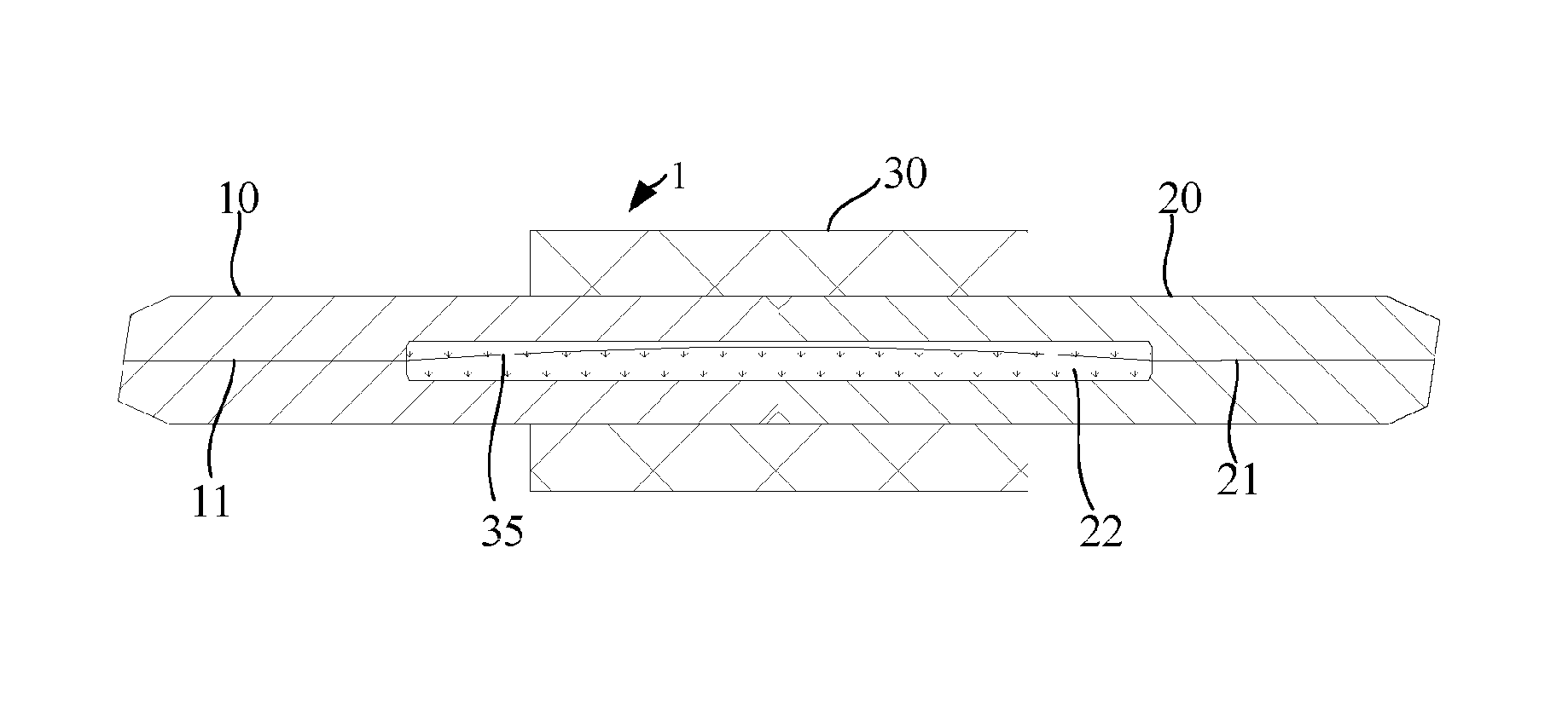
[0045]As shown in FIG. 1 to FIG. 3, an optical fiber grating tracker 1 according to an embodiment includes a first stub 10, a second stub 20, an optical fiber grating 35, and a connection part 30. The connection part 30 has a through hole 31. The first stub 10 has a first optical fiber cavity 11. The second stub 20 has a second optical fiber cavity 21. The first stub 10 is inserted into one end 32 of the through hole 31. The second stub 20 is inserted into the other end 33 of the through hole 31. One end of the first stub 10 in the through hole 31 is provided with a first cavity 12. One end of the second stub 20 in the through hole 31 is provided with a second cavity 22. The optical fiber grating 35 is in the first cavity 12 and the second cavity 22. The first cavity 12 and the second cavity 22 are filled with a waterproof material 34. The optical f...


PUM


Abstract

An optical fiber grating tracker includes a first stub, a second stub, an optical fiber grating, and a connection part. The connection part has a through hole. The first stub is inserted into one end of the through hole. The second stub is inserted into the other end of the through hole. An interval exists between the first stub and the second stub. The optical fiber grating is in the through hole and in the interval. A space in the through hole is filled with a waterproof material. The optical fiber grating tracker and the method for detecting an optical fiber line fault can detect an optical fiber fault from an optical fiber truck to the optical fiber grating tracker through an optical splitter, and meanwhile do not affect normal communication of an original optical communication network.

Description

CROSS REFERENCE TO RELATED APPLICATIONS[0001]This application claims the CN priority of CN 201210358287.6, filed on Sep. 24, 2012. The contents of CN 201210358287.6 are all hereby incorporated by reference.BACKGROUND[0002]1. Technical Field[0003]The present application relates to the field of optical communications, and in particular, to an optical fiber grating tracker and a method for detecting an optical fiber line fault.[0004]2. Related Arts[0005]An optical fiber grating is an optical fiber passive device, and actually an optical fiber, where a fiber core of the optical fiber has a structure having a refractive index changed periodically or called a Bragg reflector in the optical fiber core. By means of ultraviolet light sensitivity of an optical fiber material, through methods such as a two beam interference method and a phase mask method, a bare fiber is exposed from the side surface to an interference pattern of an ultraviolet light beam, so as to write the interference patte...

Claims


Application Information

Patent Timeline
IPC IPC(8): G02B6/34G01N21/17
CPCG01N21/17G02B6/34G02B6/38G02B6/3845G02B6/3846G01M11/31H04B10/071
Inventor WEI, GUANGYUAN
Owner T&S COMM
Learn More