Composite isolating transformer

a transformer and isolating technology, applied in the direction of transformer/inductance coil/winding/connection, transformer/inductance details, electrical equipment, etc., can solve the problem of high voltage coil generating creeping discharge, transformer damage, and inability to wind the primary coil and secondary coil

Inactive Publication Date: 2014-03-27
INNOTRANS TECH
View PDF3 Cites 5 Cited by
  • Summary
  • Abstract
  • Description
  • Claims
  • Application Information

AI Technical Summary

Benefits of technology

[0005]The primary object of the present invention is to provide a transformer structure that can isolate creeping discharge and allow winding of the high voltage coil and low voltage coil

Problems solved by technology

The high voltage coil generates a creeping discharge problem upon receiving an input voltage.
If this creeping discharge is not being isolated, the lower voltage coil could be broken down by the high voltage to result in damage of the transfor

Method used


Image

  • Composite isolating transformer
  • Composite isolating transformer
  • Composite isolating transformer

Examples


Embodiment Construction

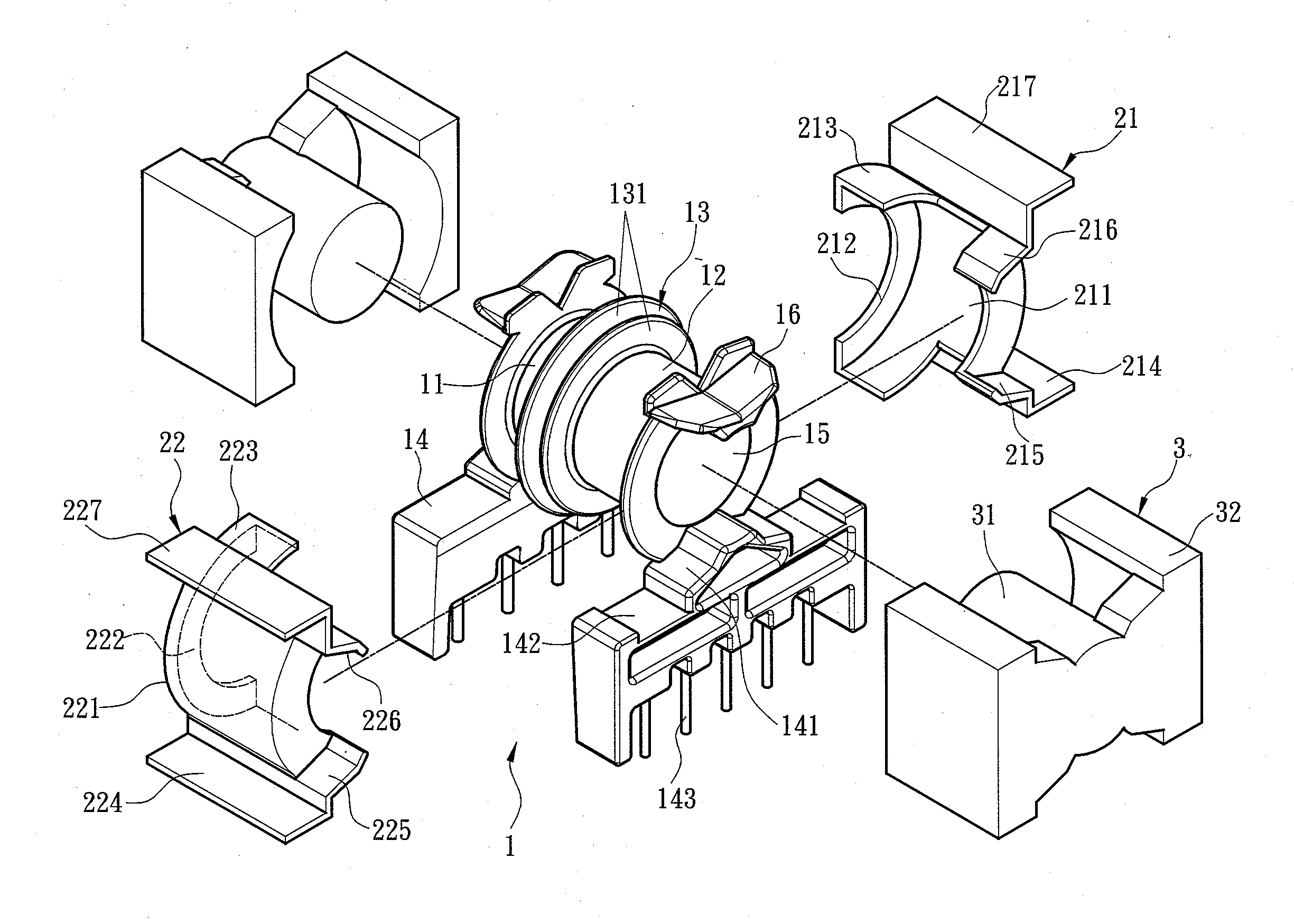
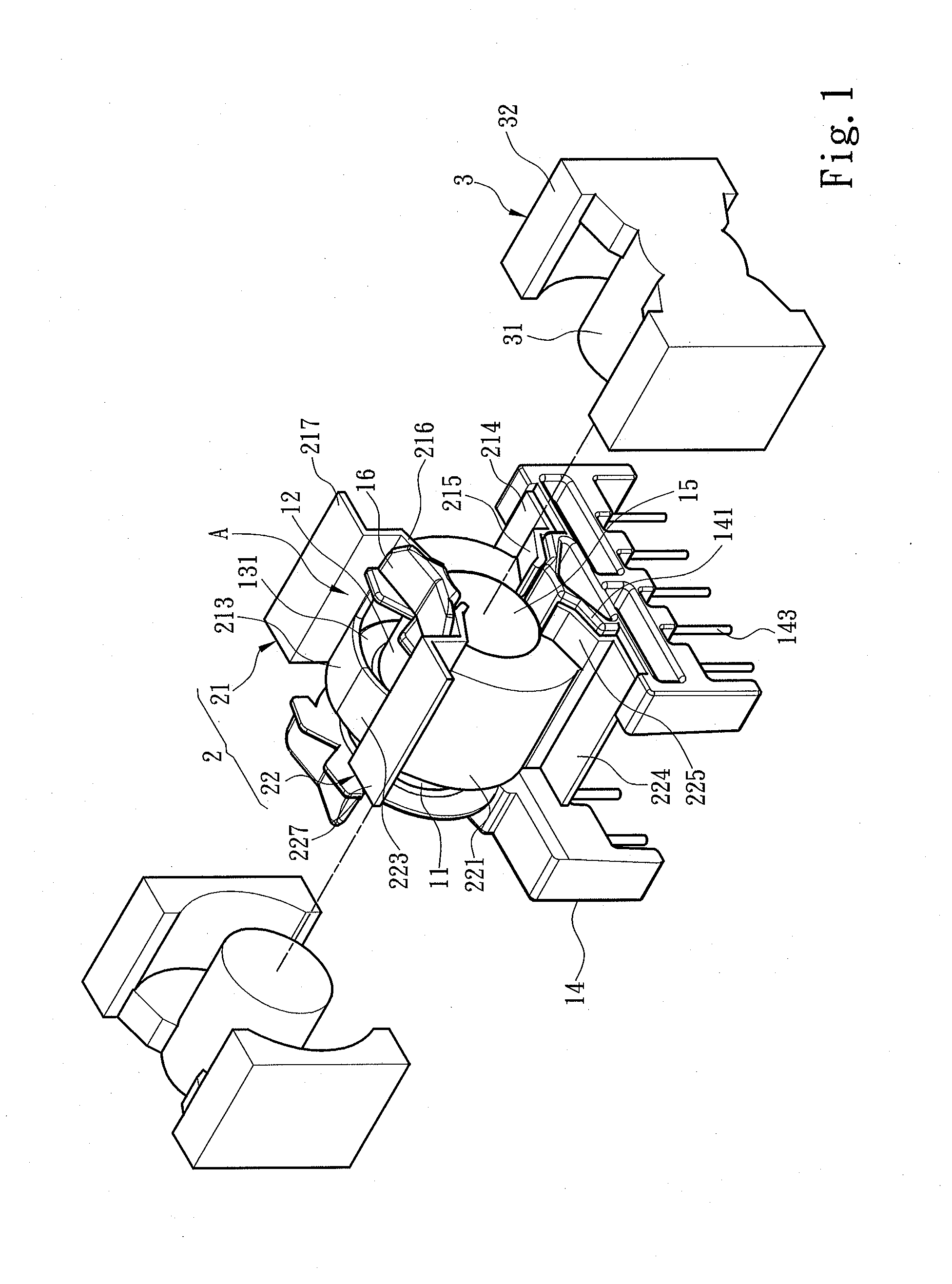
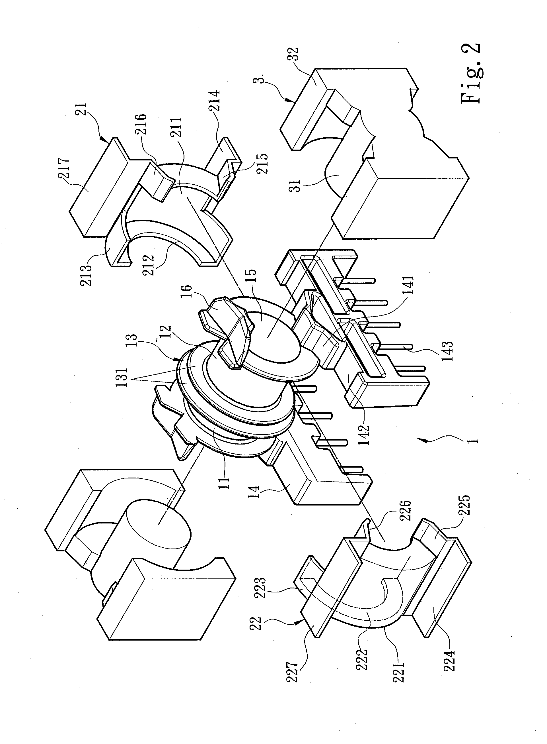
[0024]Please refer to FIGS. 1, 2 and 3 for an embodiment of a composite isolating transformer of the invention. It includes a main winding rack 1 and a support rack 2 mounted onto the main winding rack 1. The main winding rack 1 has two winding portions 11 and 12 coaxially formed to hold respectively a primary coil 41 and a secondary coil 42, a separating portion 13 located between the two winding portions 11 and 12 to separate them, two connecting portions 14 at two opposite ends of the two winding portions 11 and 12, and an installation channel 15 running through the two winding portions 11 and 12 to hold an iron core set 3 which is magnetically coupled with magnetic paths generated by the primary coil 41 and secondary coil 42 when electricity is provided.

[0025]More specifically, the separating portion 13 includes two spacers 131 between the two winding portions 11 and 12, and a separating section 132 between the two spacers 131 to separate the two winding portions 11 and 12. The ...


PUM


Abstract

A composite isolating transformer includes a main winding rack and a support rack. The main winding rack includes two winding portions coaxially formed to hold respectively a primary coil and a secondary coil, and a separating portion between the two winding portions. The support rack includes a first support half member and a second support half member coupling together to encase at least one winding portion. The first and second support half members have respectively a first cover and a second cover to cover two lateral sides of the winding portion, respectively a first insulating portion and a second insulating portion corresponding to the separating portion and extending towards the separating section to couple together, and respectively a first isolating portion and a second isolating portion extended from the first and second insulating portions towards the winding portion to cover another two lateral sides of the winding portion.

Description

FIELD OF THE INVENTION[0001]The present invention relates to an isolating transformer and particularly to a composite isolating transformer.BACKGROUND OF THE INVENTION[0002]In most types of electric products implemented through electric power transformers play an important role in power transformation or signal isolation. A general transformer has various electric parameters when in use that are preset at the stage of research and production, such as power conversion ratio, mutual inductance value generated when winding coils are energized or loss occurring when the current passes through the winding coils. Then design is made for the transformer structure such as winding coil, winding rack or iron core according to the aforesaid electric parameters. By adjusting the coil ratio of the winding coils or interval between the winding zones on the winding rack, the produced transformer can generate the electric parameters the same as the original design.[0003]A conventional transformer i...

Claims


Application Information

Patent Timeline
IPC IPC(8): H01F27/30
CPCH01F27/306H01F27/263
Inventor HU, JEN-YAO
Owner INNOTRANS TECH
Why Eureka
Try Eureka