Bound document having binding strip with spacer

a technology of binding strip and spacer, which is applied in the field of bound documents with binding strip with spacer, can solve the problems of affecting the appearance and function of conventional soft or hard cover books, affecting the quality of books, and the sheets in the binders of the three-ring type, such as the three-ring type binders, and achieving the effects of convenient storage, convenient storage, and convenient retrieval

Inactive Publication Date: 2014-03-27
EASTMAN KODAK CO
View PDF7 Cites 0 Cited by
  • Summary
  • Abstract
  • Description
  • Claims
  • Application Information

AI Technical Summary

Benefits of technology

[0020]An advantage of this invention is that a bound document as claimed has a more professional appearance, since the fasteners are concealed. Various aspects conceal fastener protrusions on both sides of a sheet block. Various aspects provide a straight, even spine, which makes the bound document easier to store on, and retrieve from, a bookshelf.

Problems solved by technology

Clamp- and ring-type binders, such as three-ring binders, do not have the appearance and function of conventional soft or hard covered books.
Furthermore, these binders require a margin be provided in which perforations or other mounting features can be punched or placed; this margin can occupy a considerable area that could otherwise be printed with content.
Moreover, sheets in these binders, e.g., three-ring binders, are susceptible to damage that permits pages to fall out, possibly without detection.
Such wrinkles or bubbles would be perceptible to the touch of a person holding the book by the spine to read it, and could cause undesirable distraction or an impression of a lower-quality product.
However, this scheme can leave a noticeable offset (at least the thickness of the matrix) between the endpapers at either end of the book.
This can be objectionable.
Binding by this scheme is therefore limited in use, time-consuming, and tedious.
However, this scheme uses an adhesive spine, so does not provide full wrap-around covers.

Method used


Image

  • Bound document having binding strip with spacer
  • Bound document having binding strip with spacer
  • Bound document having binding strip with spacer

Examples


Embodiment Construction

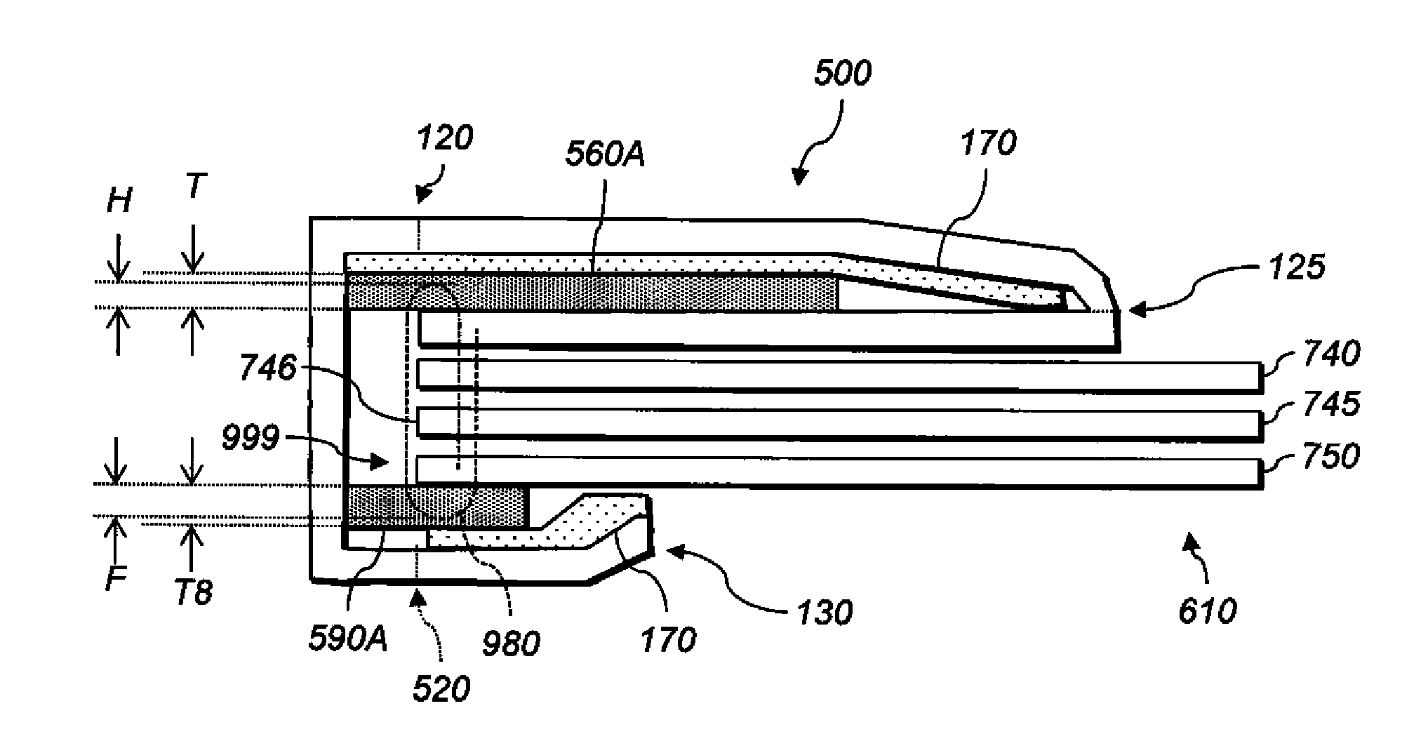
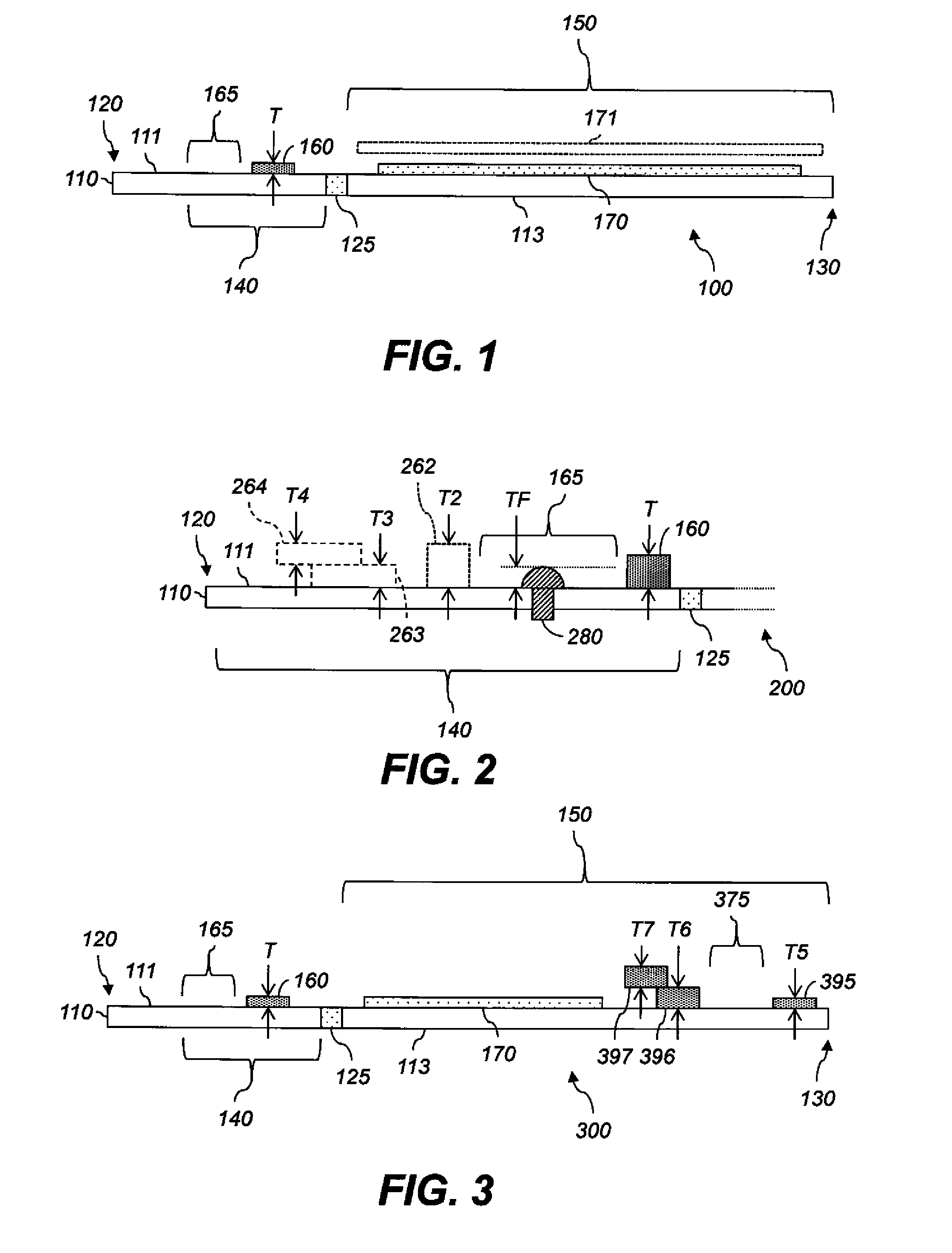
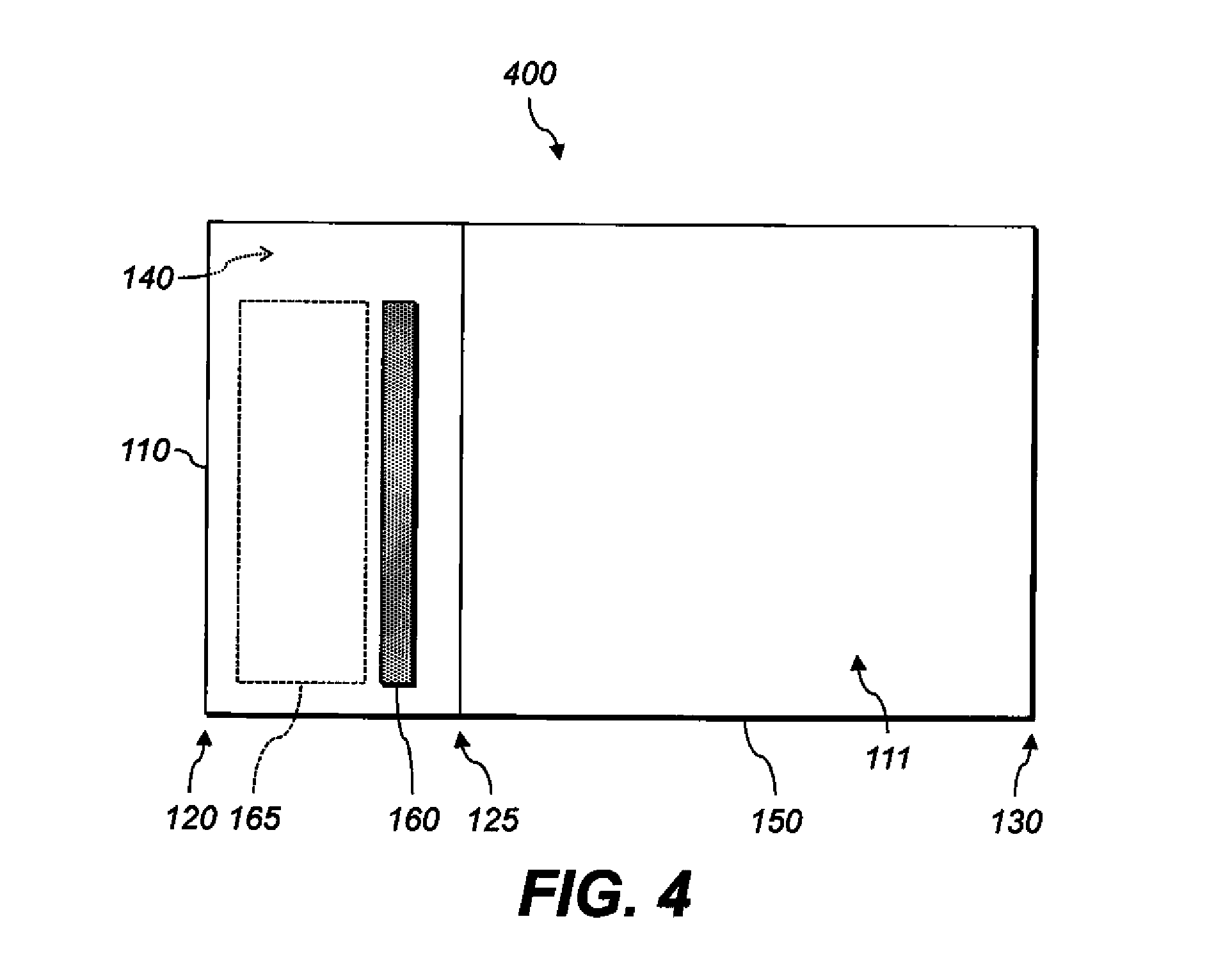
[0028]Reference is made to commonly-assigned U.S. Pat. No. 8,182,188, incorporated herein by reference.

[0029]In the following description, some aspects will be described in terms that would ordinarily be implemented as software programs. Those skilled in the art will readily recognize that the equivalent of such software can also be constructed in hardware. Because image manipulation algorithms and systems are well known, the present description will be directed in particular to algorithms and systems forming part of, or cooperating more directly with, methods described herein. Other aspects of such algorithms and systems, and hardware or software for producing and otherwise processing the image signals involved therewith, not specifically shown or described herein, are selected from such systems, algorithms, components, and elements known in the art. Given the system as described herein, software not specifically shown, suggested, or described herein that is useful for implementati...


PUM


Abstract

A bound document has front, back, and interior sheets with spine edges. The document has a binding strip and fasteners binding the sheets and the binding strip together. The strip has a flexible substrate with a face-attachment portion through which the fasteners are driven, and a wraparound portion that is bent so adhesive on the wraparound portion contacts the back sheet farther from the spine edge of the book than the feet of the fasteners. The strip also has a first spacer affixed to the interior surface opposite the face-attachment portion so that a fastener area is defined, the spacer at least as thick as the protrusion of the heads of the fasteners above the face-attachment portion.

Description

CROSS-REFERENCE TO RELATED APPLICATIONS[0001]This application is co-filed with and has related subject matter to U.S. patent application Ser. No. ______, (attorney docket no. K001223), filed herewith, titled “BINDING STRIP INCLUDING SPACER;” and U.S. patent application Ser. No. ______, (attorney docket no. K001274), filed herewith, titled “MAKING BOUND DOCUMENT HAVING FASTENER AND SPACER;” each of which is incorporated herein by reference in its entirety.[0002]This application has related subject matter to U.S. patent application Ser. No. 13 / 558,776, filed Jul. 26, 2012, titled “PRODUCING BOUND DOCUMENT HAVING INNER COVER SHEET.”FIELD OF THE INVENTION[0003]This invention relates to books with printed covers.BACKGROUND OF THE INVENTION[0004]Books and photo albums are commonly assembled from single- and double-sided printed documents and photographs. Traditional bookbinding methods include gluing or stitching a set of pages together along one edge. This bound edge is then attached to ...

Claims


Application Information

Patent Timeline
Patent Type & Authority Applications(United States)
IPC IPC(8): B42D1/06
CPCB42D1/06B42B5/08B42C9/0056B42D1/04
Inventor NO, YOUNGSCHULZE-HAGENEST, DETLEF
Owner EASTMAN KODAK CO
Why Eureka
Try Eureka