
Method and apparatus for laser ablation under ultrasound guidance

a laser ablation and ultrasound guidance technology, applied in the field of laser ablation under ultrasound guidance, can solve the problems of large temperature gradient, very unsafe temperature of surrounding tissue, and difficult to achieve the effect of reducing the risk of infection

Inactive Publication Date: 2014-03-20
CONVERGENT LIFE SCI
View PDF4 Cites 18 Cited by
  • Summary
  • Abstract
  • Description
  • Claims
  • Application Information

AI Technical Summary

Benefits of technology

The patent text describes a new method and device for performing targeted laser ablation to treat medical conditions such as BPH and prostate cancer. The invention allows for precise delivery of laser energy to the targeted tissue while measuring temperature changes without the need for real-time analysis of MRI images. This method and device can also be used with ultrasound guidance and can control the ablation sources to localize the tissue ablation. The invention solves the problem of uncontrolled ablation and damage to surrounding structures during thermal ablation procedures.

Problems solved by technology

When trying to localize the ablation, cryotherapy suffers from the disadvantage that the temperature gradient is very large from the body temperature to the ablation temperature.
As a result, while the tissue is being locally cooled, the surrounding tissue also cool down to very unsafe temperatures.
The ablation is thus hard to control and causes irreparable damage to healthy tissue.
The traditional drawback to using laser ablation is that it cannot be performed under ultrasound guidance since traditional ultrasound does not provide thermometry information.
However, this method is cumbersome, very expensive, and requires prolonged access to MR gantry, which makes it an unfeasible procedure for a vast majority of surgeons.
In addition, the learning curve to perform a laser ablation in MR gantry can be very steep.

Method used


Image

  • Method and apparatus for laser ablation under ultrasound guidance
  • Method and apparatus for laser ablation under ultrasound guidance
  • Method and apparatus for laser ablation under ultrasound guidance

Examples


Embodiment Construction

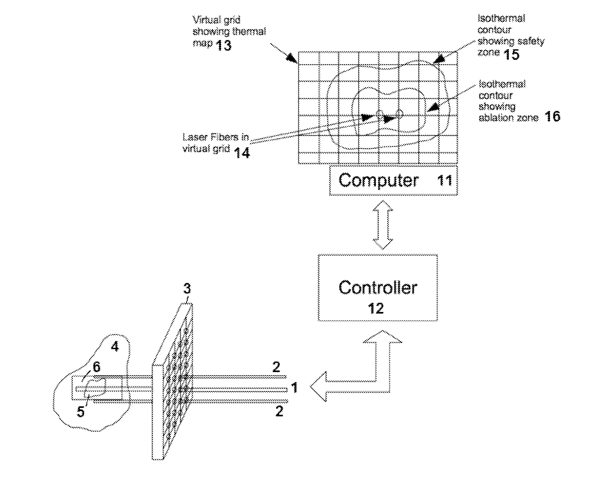
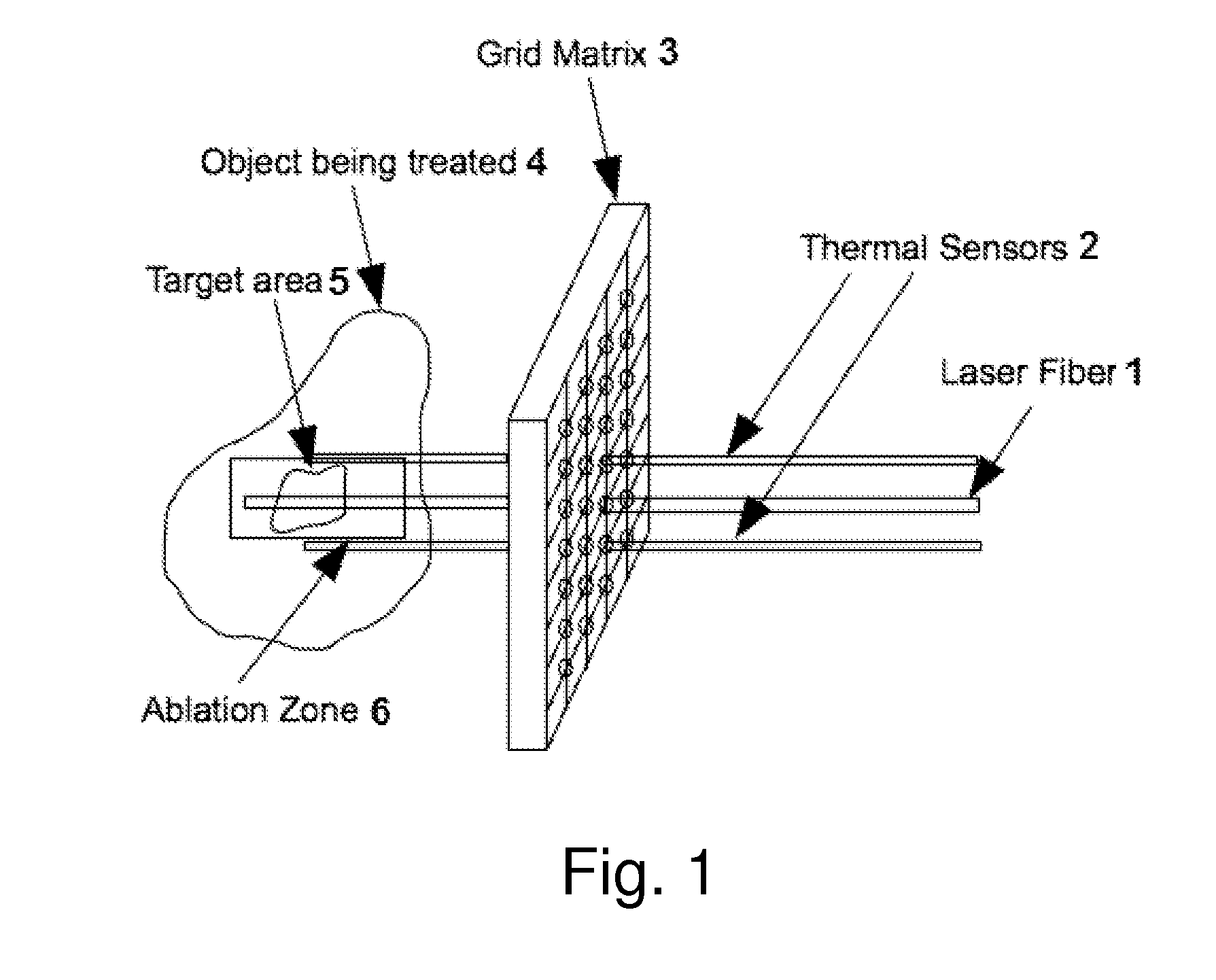
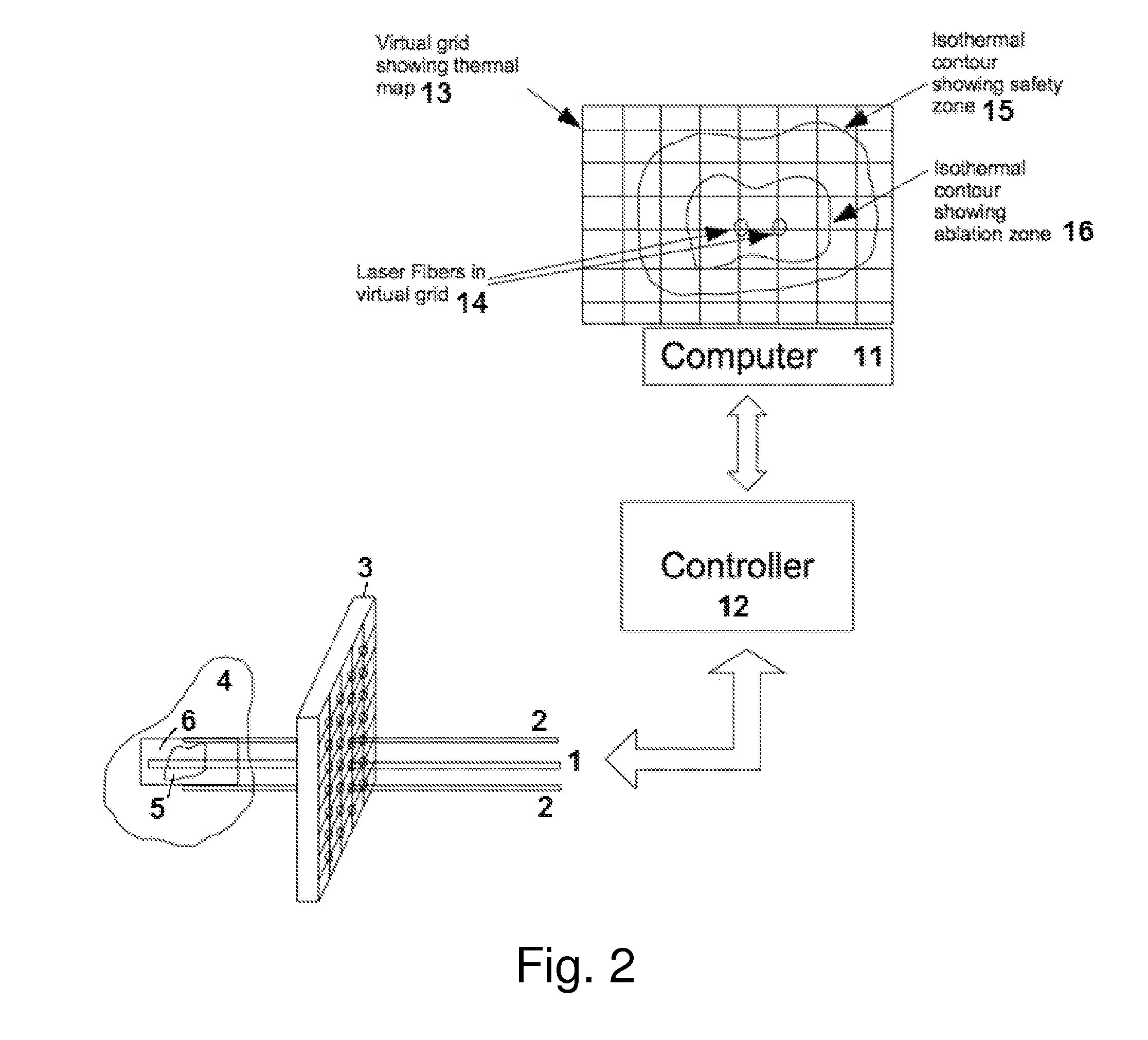
[0013]This disclosure claims methods and apparatus for performing targeted laser ablation for a medical procedure. The target may include a malignancy or benign inflammation. Specifically, the apparatus includes three essential components: i) a guidance tool that guides laser source to target region, ii) a controller that controls laser energy and iii) a computer with software that computes and displays temperature measurements.

[0014]The guidance tool used for placing laser to the target tissue may contain a tracking device such that after an initial calibration with real world, the tracking device can be manipulated to align a needle with the desired target within the tissue. The only requirement for the tracking tool is to provide a trajectory for aligning the needle.

[0015]The controller provides the interface between the computer and the laser source. The computer monitors the temperature, and in case of a software based tracking system, the trajectory of the needle. The computer...


PUM


Abstract

A method and apparatus for performing minimally-invasive image-guided laser ablation of targeted region within a tissue or organ comprising the following: A guidance tool that can guide laser source to a predefined target region from a planning image; A controller that can control energy from laser source, duration of its application and dosage of energy from laser source; and a computer with software that can compute thermometry based on precise location and duration of application or dosage of the laser source. The computer receives signal from controller and can control or shut-off laser energy.

Description

CROSS REFERENCE TO RELATED APPLICATIONS[0001]The present application is a non-provisional of U.S. Provisional Patent Application 61 / 700,273, filed Sep. 12, 2012, the entirety of which is expressly incorporated herein by reference.BACKGROUND OF THE INVENTIONPRIOR ART[0002]U.S. Pat. No. 8,155,416, issued on Apr. 10, 2012 for invention titled “Methods and apparatuses for planning, performing, monitoring and assessing thermal ablation,” discloses a thermal ablation system using an x-ray system to measure temperature changes throughout a volume of interest in a patient. Image data sets captured by the x-ray system during a thermal ablation procedure provide temperature change information for the volume being subjected to the thermal ablation. However, the invention does not disclose a method of using a guidance tool or tracking method for thermal ablation. Also, there are no claims on performing the thermal ablation under ultrasound guidance with real time thermal monitoring or multi-mod...

Claims


Application Information

Patent Timeline
Patent Type & Authority Applications(United States)
IPC IPC(8): A61B18/22
CPCA61B18/22A61B10/00A61B2017/00274A61B10/0241A61B2090/364A61B90/361A61B34/10A61B2034/107A61B2090/378A61B2090/365A61B10/02A61B2018/2005A61B18/20A61N5/0601A61N2005/0612A61N2005/063A61N5/0625A61N2005/1012A61B34/20A61B90/39
Inventor KUMAR, DINESHVOHRA, AMITSPERLING, DANIEL S.
Owner CONVERGENT LIFE SCI
Learn More