
Thermal hydrogen generator using a metal hydride and thermite

a technology of metal hydride and thermite, which is applied in the direction of instruments, transportation and packaging, and explosives, can solve the problems of simple inefficiency, inaccuracy of spatial data, and asset availability, and achieve the effects of high efficiency, very small volume, and very rapid hydrogen generation

Active Publication Date: 2014-03-20
ANASPHERE
View PDF2 Cites 4 Cited by
  • Summary
  • Abstract
  • Description
  • Claims
  • Application Information

AI Technical Summary

Benefits of technology

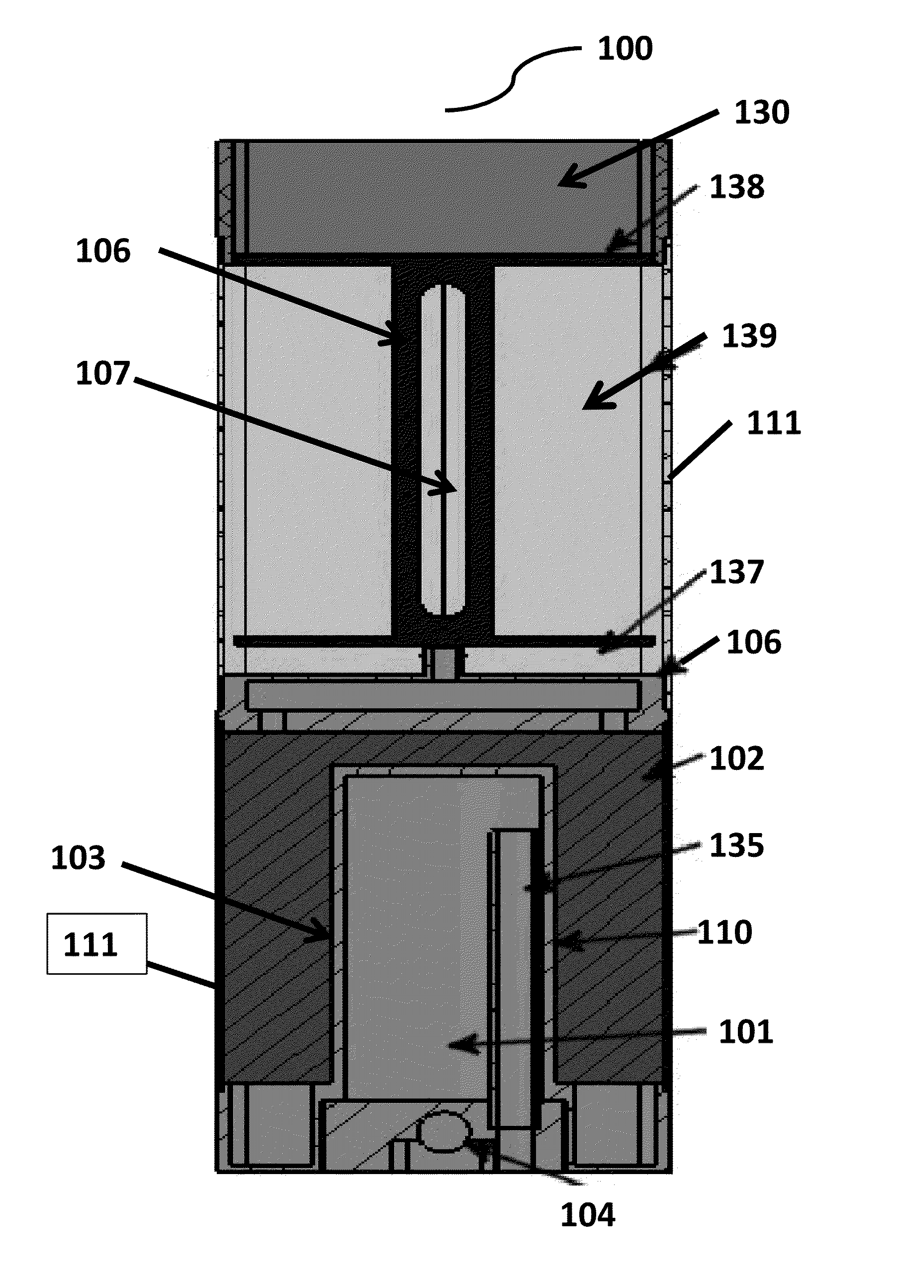
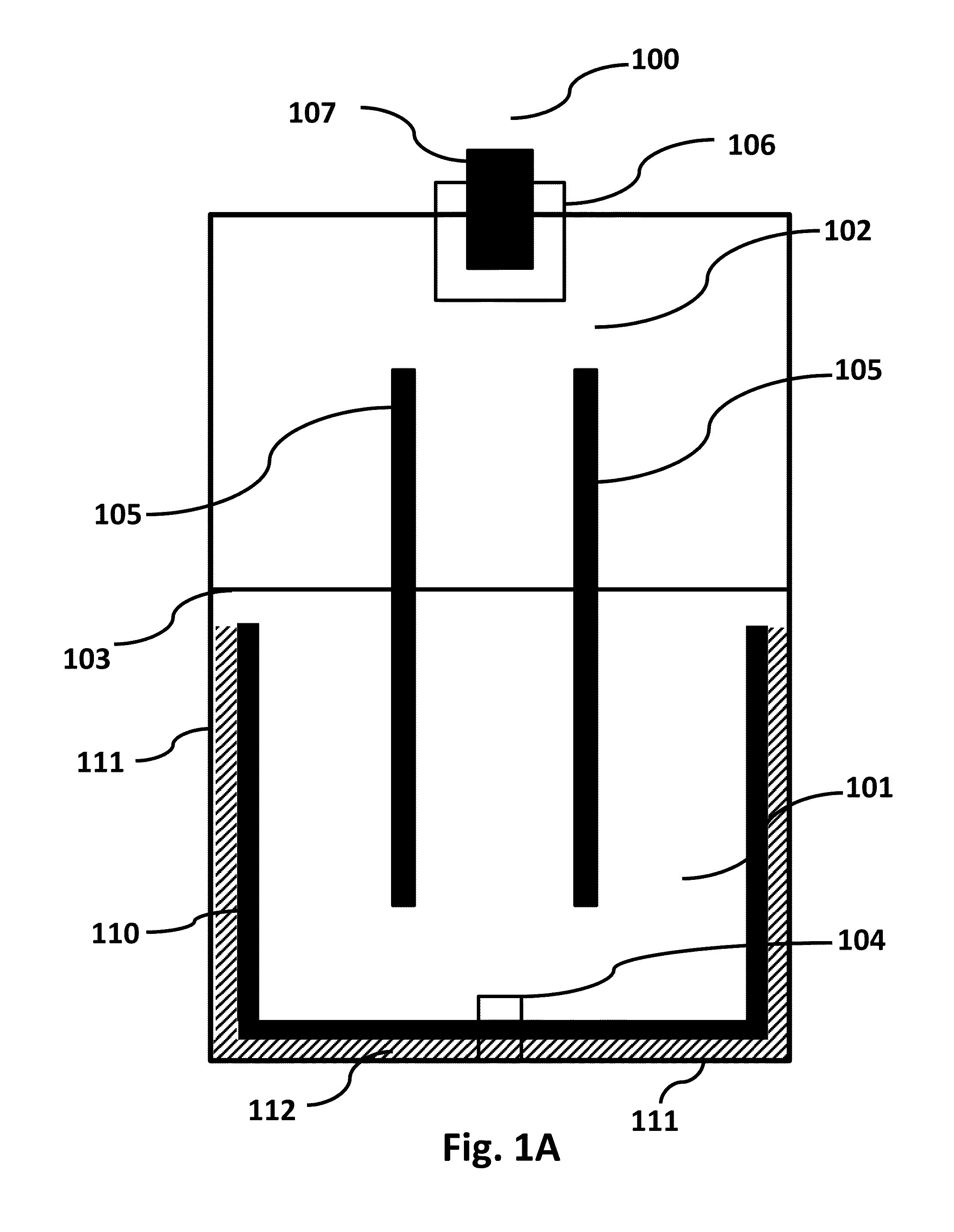
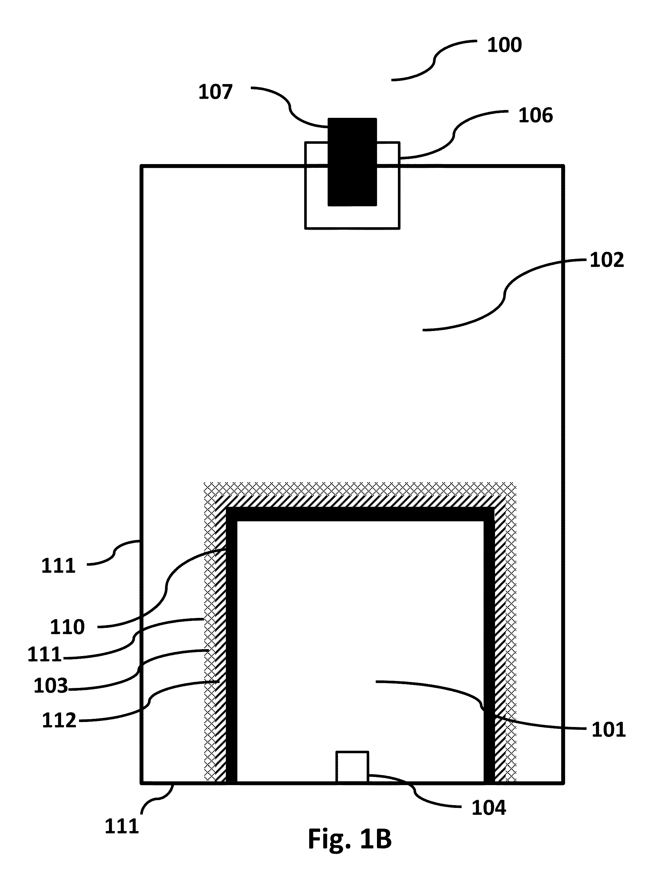
The present invention provides a way to make hydrogen gas quickly and in a small volume. This makes the system small and lightweight. This is beneficial for quickly filling meteological balloons.

Problems solved by technology

The major drawbacks affecting these approaches can include spatial inaccuracy (in the case of balloon-borne or falling sensors), asset availability (in the case of dedicated measurement aircraft), and simple inefficiency.
Several challenges are faced in the deployment of sondes from countermeasure dispensing systems.
The first challenge is that countermeasure systems are small due to the limited space on military aircraft.
Another challenge in the development of a upsonde system is the necessity of being able to rapidly fill a balloon, such as a weather balloon, with hydrogen gas (H2) so that the upsonde can begin rising immediately after being deployed from the aircraft.
There are many remote areas in the world where it is impractical or impossible to transport hydrogen or helium cylinders, or set up hydrogen generators.
Key disadvantages of this approach include the need for external electrical power, pure water, size and weight of the equipment, and the relatively slow rate of the electrolytic reaction.
Disadvantages of this approach include the size and weight of the equipment, and the need for precise thermal control of the catalytic reactor.
However, several problems present themselves with regard to a miniaturized approach, including maintaining the catalyst conditioning in storage (such as, kept under a hydrogen atmosphere), having a large enough reactor bed to achieve sufficiently fast hydrogen generation, driving a methanol / water solution through the reactor bed, and preheating the methanol / water solution to a vapor at 230 degrees Celsius.
Key disadvantages of this approach include size and weight of the equipment, as well as the comparatively demanding need to store ammonia in liquid forms in cases where volume is at a premium.
While methods to simply generate hydrogen gas are many, none of the systems can generate hydrogen gas rapidly from a lightweight, small volume system.
The system can therefore be small and lightweight.

Method used


Image

  • Thermal hydrogen generator using a metal hydride and thermite
  • Thermal hydrogen generator using a metal hydride and thermite
  • Thermal hydrogen generator using a metal hydride and thermite

Examples


examples

[0077]The thermite reaction produces a large amount of heat in a short period of time from a small volume of material. In an example implementation using 38.5 g of thermite, the thermite reaction releases nearly 152,988 J of energy over a period of about 10 seconds, or 15,299 J / sec.

[0078]Further to the volume efficiency of this approach, the hydrogen source, a metal hydride, is a very volume efficient source of hydrogen gas (H2). A test filling of a balloon was performed. The final balloon volume was measured at approximately 42 liters at the conclusion of the test. Given ambient pressure (0.82 atm) and temperature (300 degrees Kelvin or 27 degrees Celsius), this corresponded to 1.40 mole of hydrogen being produced. Working from the reactions presented above, the 30 g of LiAlH4 should have yielded 1.18 moles of hydrogen if only the first two reactions went to completion (which is the design criterion), or 1.57 moles if all three reactions went to completion. The measured value of 1....


PUM


Abstract

This invention relates to a thermal hydrogen generator and a process and system for generating hydrogen gas, more specifically to a process and system for generating hydrogen gas by thermally decomposing a metal hydride.

Description

CROSS REFERENCE TO RELATED APPLICATION[0001]The present application claims the benefits of U.S. Provisional Application Ser. No. 61 / 701,721, filed Sep. 17, 2012, entitled “Thermal Hydrogen Generator Using a Metal Hydride and Thermite”, which is incorporated herein by this reference in its entirety.STATEMENT REGARDING FEDERALLY SPONSORED RESEARCH OR DEVELOPMENT[0002]The U.S. Government has a paid-up license in this invention and the right in limited circumstances to require the patent owner to license others on reasonable terms as provided for by the terms of Contract No. FA9302-12-M-0001 awarded by the United States Air Force.TECHNICAL FIELD[0003]This invention relates to a thermal hydrogen generator and a process and system for generating hydrogen, more specifically to a process and system for generating hydrogen by thermally decomposing a metal hydride.BACKGROUND OF INVENTION[0004]Present methods to gather in-situ meteorological data include launching conventional balloon-borne ra...

Claims


Application Information

Patent Timeline
IPC IPC(8): G01W1/08B64B1/58
CPCB64B1/58G01W1/08C06B45/00C06B43/00B01J7/00C01B3/04B64B1/62
Inventor BOGNAR, JOHN A.
Owner ANASPHERE
Learn More