
Flash Redirecting Recoil Compensator

a recoil compensator and flash technology, applied in the field of flash redirecting recoil compensators, can solve the problems of affecting the accuracy of all subsequent shots, and destroying the sight picture at night, so as to achieve the effect of reducing the risk of injury to a soldier or law enforcement agent, and reducing the risk of injury

Active Publication Date: 2014-03-20
MORRIS JR JAMES
View PDF4 Cites 15 Cited by
  • Summary
  • Abstract
  • Description
  • Claims
  • Application Information

AI Technical Summary

Benefits of technology

The present invention is a flash redirecting recoil compensator that reduces recoil and prevents the flash of the firearm from completely obscuring the sight picture. It aims to provide maximum efficiency to the shooter by allowing them to maintain their sight picture and keep the firearm on target. The invention can be easily installed on firearms without significant modification and is compatible with combat holsters. It is designed to be installed on firearms without requiring significant modification and is compatible with combat holsters. The invention redirects the hot gas and unburned powder expelled from the firearm, preventing the flash from completely obscuring the sight picture. It is designed to be attached to firearms and can be used with different types of firearms.

Problems solved by technology

The forces associated with recoil can create a number of problems when a shooter is trying to maintain accuracy when firing their weapon.
While the accuracy of the first shot is largely unaffected by the recoil of the firearm, the accuracy of all subsequent shots is drastically affected, especially with fully automatic firearms.
The positive effect of recoil compensators using this configuration is accompanied by the unfortunate effect of directing the bright flash of the discharging gas and powder into the sight path of the shooter.
This is extremely unfortunate when the shooter is in lowlight conditions as the bright flash of light directed into the sight picture can cause night blindness and loss of the sight picture entirely.
This adverse effect can even be life threatening to a soldier or law enforcement agent who is relying upon a clear line of sight to the target resolve deadly situations.

Method used


Image

  • Flash Redirecting Recoil Compensator
  • Flash Redirecting Recoil Compensator
  • Flash Redirecting Recoil Compensator

Examples


Embodiment Construction

[0017]All illustrations of the drawings are for the purpose of describing selected versions of the present invention and are not intended to limit the scope of the present invention.

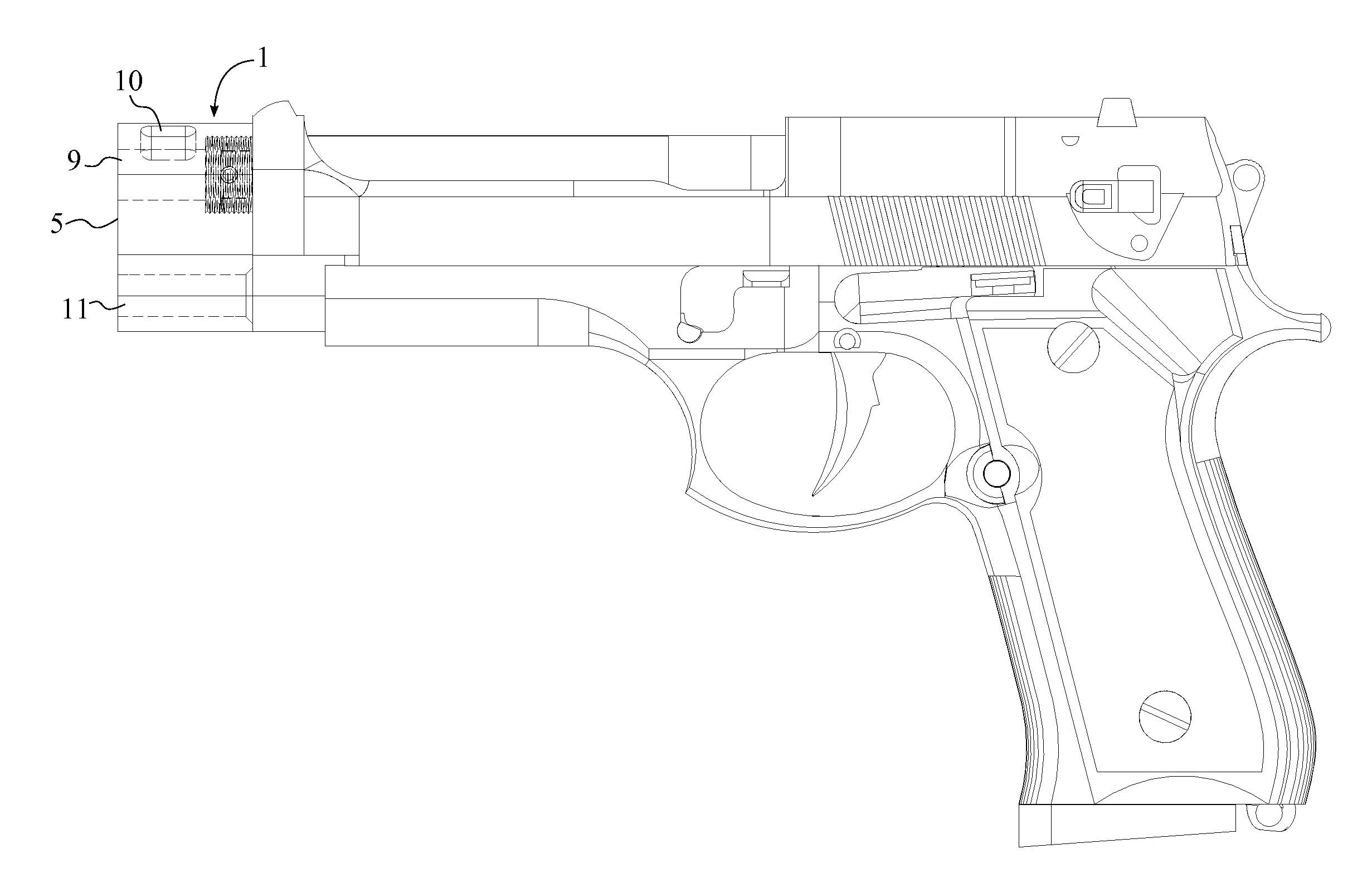
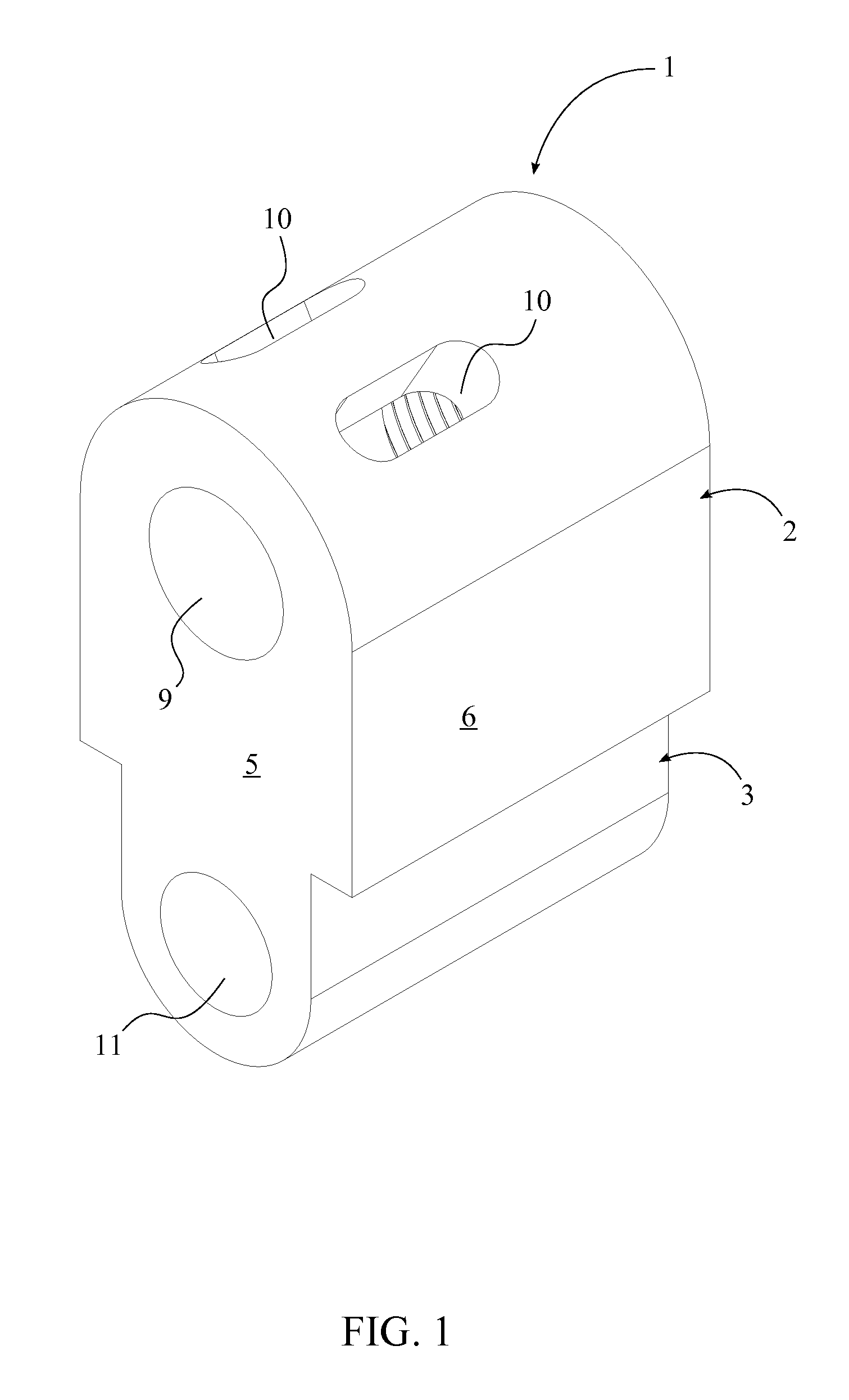
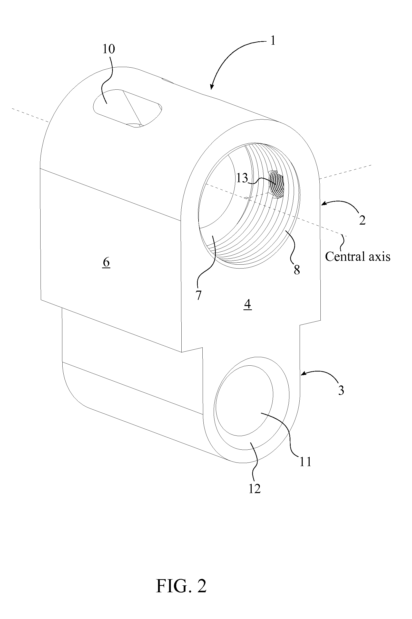
[0018]In reference to FIG. 1 and FIG. 2, the present invention is a flash redirecting recoil compensator which comprises a compensator body 1, an attachment chamber 7, a discharge chamber 9, at least two vectoring ports 10, a guide rod hole 11, and a screw hole 13. The present invention is mounted directly onto a gun barrel of a firearm without the use of an expansion chamber, where the present invention drastically reduces the recoil of the firearm while redirecting the muzzle flash away from the sight of the shooter.

[0019]In reference to FIG. 1-FIG. 5, the compensator body 1 is the primary component of the present invention as all of the other components of the present invention are either positioned or attached to the compensator body 1. The compensator body 1 comprises a top portion 2, a bottom porti...


PUM


Abstract

A flash redirecting recoil compensator for a firearm includes a compensator body that provides a platform for the rest of the components. The compensator body attaches with a firearm in order to reduce recoil force and redirect the muzzle flash away from the site of the shooter. An attachment chamber and a discharge chamber of the compensator body are positioned through a top portion of the compensator body from a rear face to a front face. The attachment chamber fastens the compensator body into the firearm while the discharge chamber provides space for the discharging bullet. At least two vectoring ports, which are traversed through the compensator body and into the discharge chamber, redirect hot gas and unspent propellants away from the firearm after the bullet is discharged as the redirection of the hot gas and unspent propellants reduce the recoil force and provide a clear shooting sight.

Description

[0001]The current application claims a priority to the U.S. Provisional Patent application Ser. No. 61 / 684,915 filed on Aug. 20, 2012.FIELD OF THE INVENTION[0002]The present invention relates generally to firearm attachments. More specifically the present invention is a flash redirecting recoil compensator which is mounted on the barrel of a firearm and thereby reduces recoil of the firearm by redirecting the hot gasses expelled from the barrel.BACKGROUND OF THE INVENTION[0003]Firearms are widely used by militaries, law enforcement agencies, and even private citizens around the world. The purpose of firearms ranges from eliminating hostile threats with vicious efficiency to upholding law and order, and even putting food on the table for some. Recoil is constant concern when discharging a firearm that is governed by the simple law of physics that every action causes an equal and opposite reaction. In the case of recoil, the action of the bullet being propelled forwards at extreme vel...

Claims


Application Information

Patent Timeline
IPC IPC(8): F41A21/36F41A21/34
CPCF41A21/34F41A21/36
Inventor MORRIS, JR., JAMES
Owner MORRIS JR JAMES
Learn More