High efficient single switch single stage power factor correction power supply

a single-stage power factor and high-efficiency technology, applied in power conversion systems, power electronics conversion, sustainable manufacturing/processing, etc., can solve the problems of reducing the efficiency of power converters, increasing the cost and device counts of converters,

Inactive Publication Date: 2014-03-13
LIN FUXIANG
View PDF19 Cites 6 Cited by
  • Summary
  • Abstract
  • Description
  • Claims
  • Application Information

AI Technical Summary

Benefits of technology

[0008]The fifth objective of the present invention is to provide a snubber circuit without loss.

Problems solved by technology

However, the PFC stage configuration increases the cost and device counts of the converter, and hence the efficiency of power converter is reduced.

Method used


Image

  • High efficient single switch single stage power factor correction power supply
  • High efficient single switch single stage power factor correction power supply
  • High efficient single switch single stage power factor correction power supply

Examples


Embodiment Construction

[0019]Before explaining the disclosed embodiment of the present invention in detail, it is to be understood that the invention is not limited in its application to the details of the particular arrangement shown since the invention is capable of other embodiments.

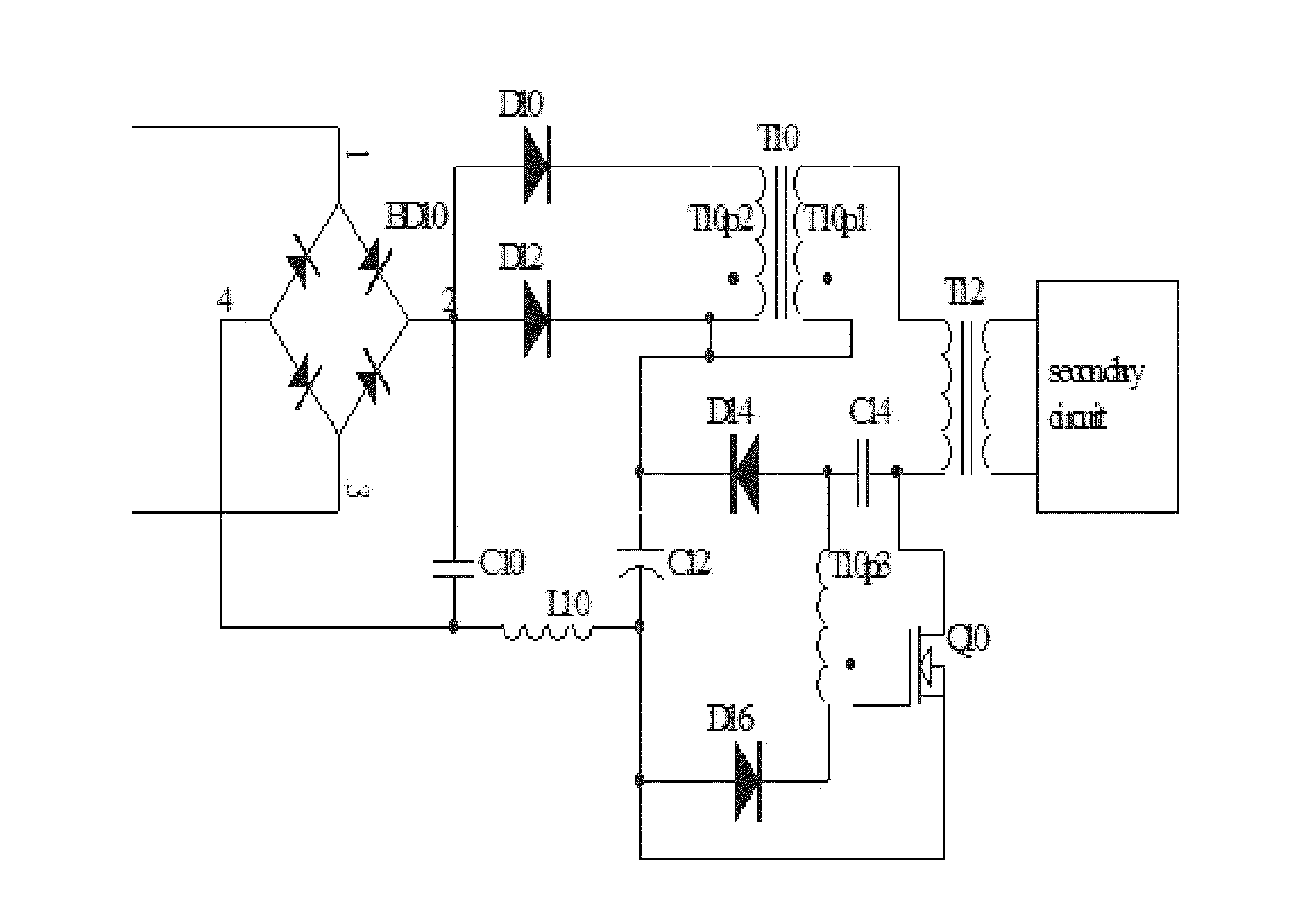
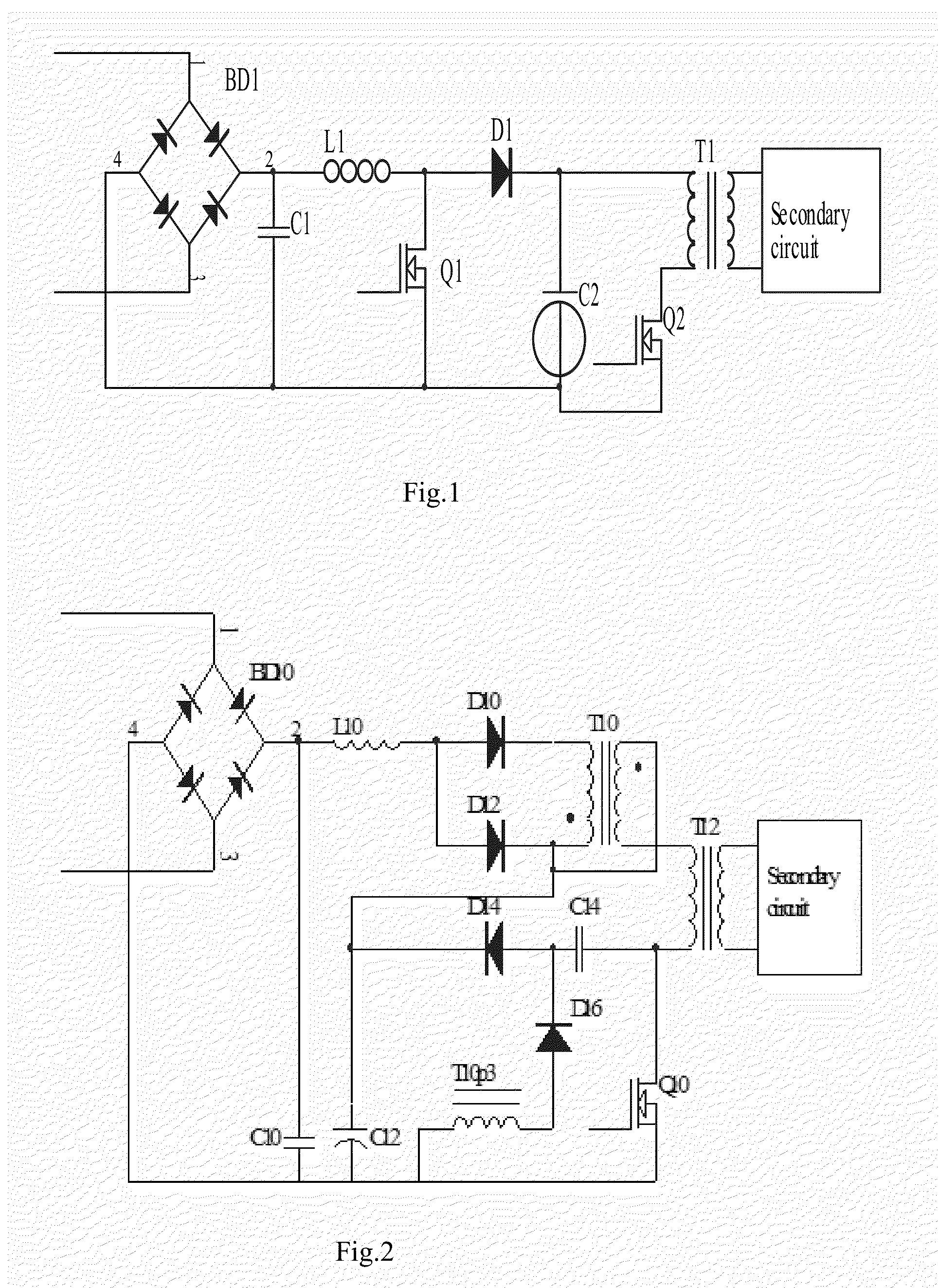
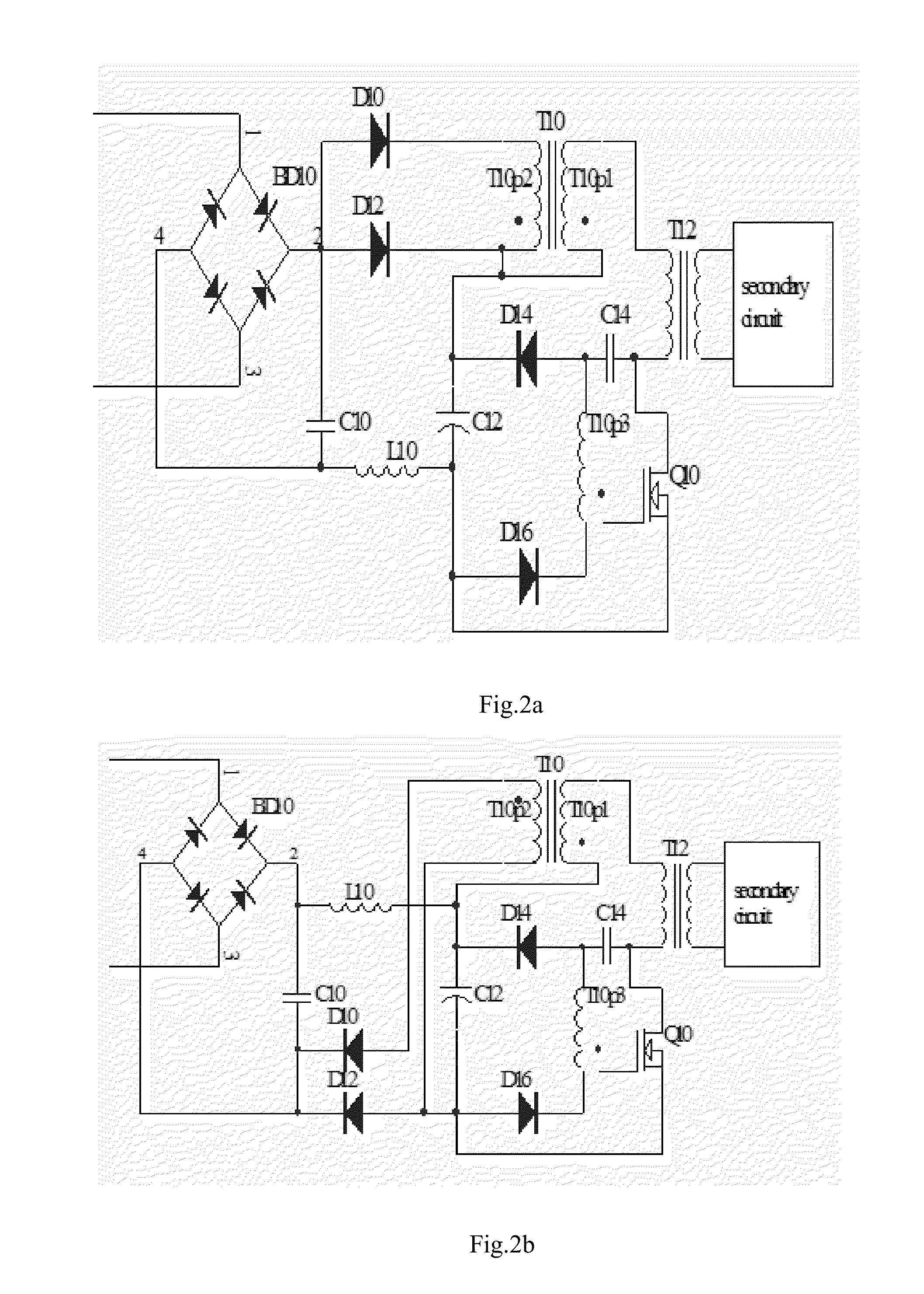
[0020]The topology of the present invention is that a (PFC) forward transformer primary winding is connected in series with the main transformer primary winding. The main transformer transfers power from the primary circuit to the secondary circuit, the forward transformer transfers power to its second winding of the forward transformer to correct the input current waveform. When switch is off, the no loss snubber circuit stores the electrical energy in the capacitor; when the switch is on, it relieves the energy to forward transformer.

[0021]Refer to FIG. 2: The circuit diagram is a power factor correction for a single switch power supply unit. The arrangement is following:

[0022]A full bridge rectifier BD 10 has output term...


PUM


Abstract

A single switch PFC power supply (including forward and fly-back power supply) in single stage has two transformers: one forward transformer, one main transformer. The main transformer transfers electrical power from the primary circuit to secondary circuit. The forward transformer is used to correct input current waveform. The two transformer's primary windings are connected in series. An extra winding of the forward transformer, a capacitor and two diodes are formed a no loss snubber circuit to enhance the efficiency of the power supply.

Description

[0001]The present invention relates to a power converter, and more particularly, to a high efficiency power factor correction (PFC) power converter in a single stage.DESCRIPTION OF THE RELATED ART[0002]Power converters have widely served to convert an unregulated power source to a regulated voltage or current. A PFC (Power Factor Correction) technique is applied to make an input current follow the waveform of an input voltage. Adding a PFC stage to the front end of a power converter substantially avoids unnecessary power loss and heat dissipation in a power contribution system.[0003]Referring to FIG. 1, a power converter having two stages, according to prior art is illustrated. A first stage is PFC stage, which includes an inductor L1, a rectifier D1 and a transistor Q1 is driven by a PFC control signal from the PFC stage. A second stage includes a transistor Q2 controlled by a control signal PWM, a transformer T1 and secondary circuitry, thus output voltage is regulated and output ...

Claims


Application Information

Patent Timeline
Patent Type & Authority Applications(United States)
IPC IPC(8): H02M1/42
CPCH02M1/42H02M1/4258Y02B70/10Y02P80/10
Inventor LIN, FUXIANG
Owner LIN FUXIANG
Why Eureka
Try Eureka