
Motor control apparatus, motor control method, control system, and position estimation method to be used in control system

a technology of motor control and position estimation, which is applied in the direction of electric programme control, program control, instruments, etc., can solve the problems of robot instability, robot oscillation, and inability to increase the torque command more than a predetermined level, and achieve the effect of reducing the speed of the motor and high-precision position estimation

Active Publication Date: 2014-03-13
SANKYO SEIKI MFG CO LTD
View PDF7 Cites 20 Cited by
  • Summary
  • Abstract
  • Description
  • Claims
  • Application Information

AI Technical Summary

Benefits of technology

The motor control device described in this patent allows for smooth operation of a robot even if there are sudden changes in voltage or power supply. The control method also allows for precise position estimation without reducing the speed of the motor.

Problems solved by technology

However, the torque command cannot be increased more than a predetermined level due to physical restrictions of the motor driver, etc.
For this reason, if the original voltage to be applied to the motor driver drops dramatically, not only may the robot not be operated for desired motions, but also a so-called windup phenomenon may occur under the influence of an integrating function that the PI controller owns, causing to the robot to show unstable behaviors such as oscillating movements.
However, if the motor is halted to stop the robot when an instantaneous voltage drop occurs, a long recovery time is required to restart the robot, degrading productivity.
When a robot is used in a factory in particular where the electric power supply is poor, productivity will be greatly decreased if the robot is stopped every time an instantaneous voltage drop occurs.

Method used


Image

  • Motor control apparatus, motor control method, control system, and position estimation method to be used in control system
  • Motor control apparatus, motor control method, control system, and position estimation method to be used in control system
  • Motor control apparatus, motor control method, control system, and position estimation method to be used in control system

Examples


first embodiment

Major Effect of First Embodiment

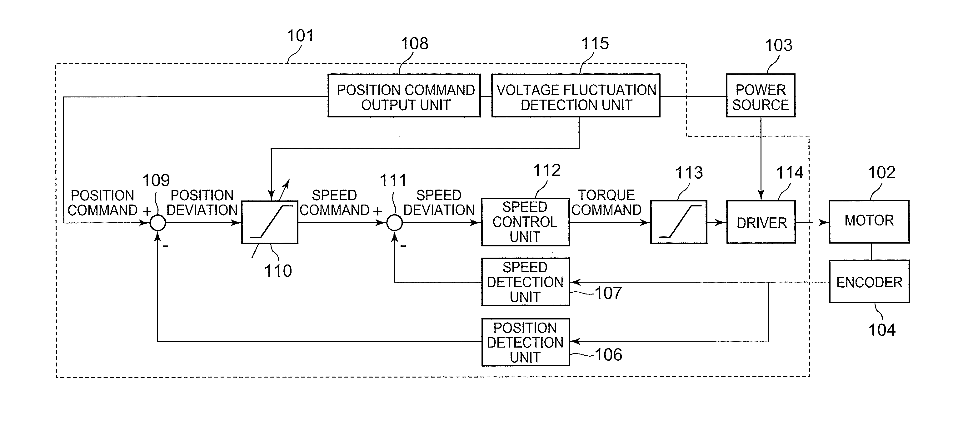
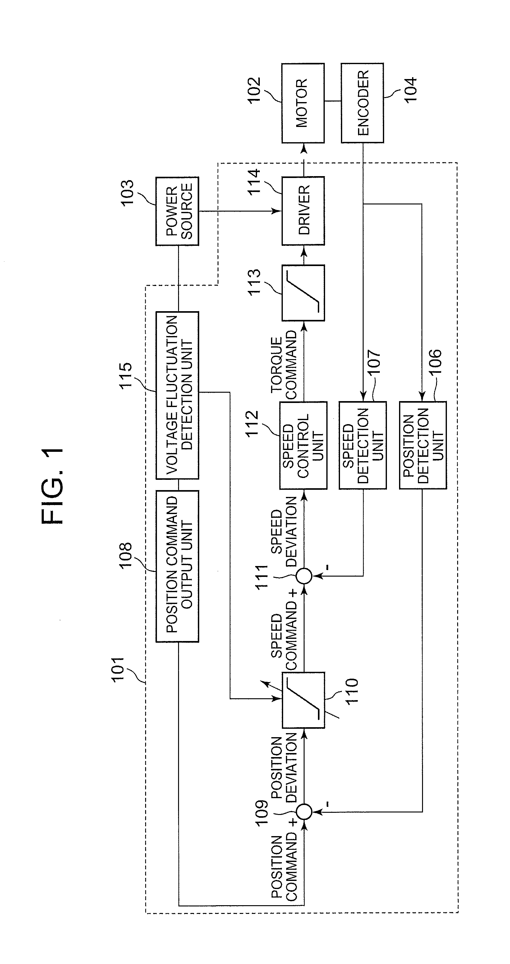
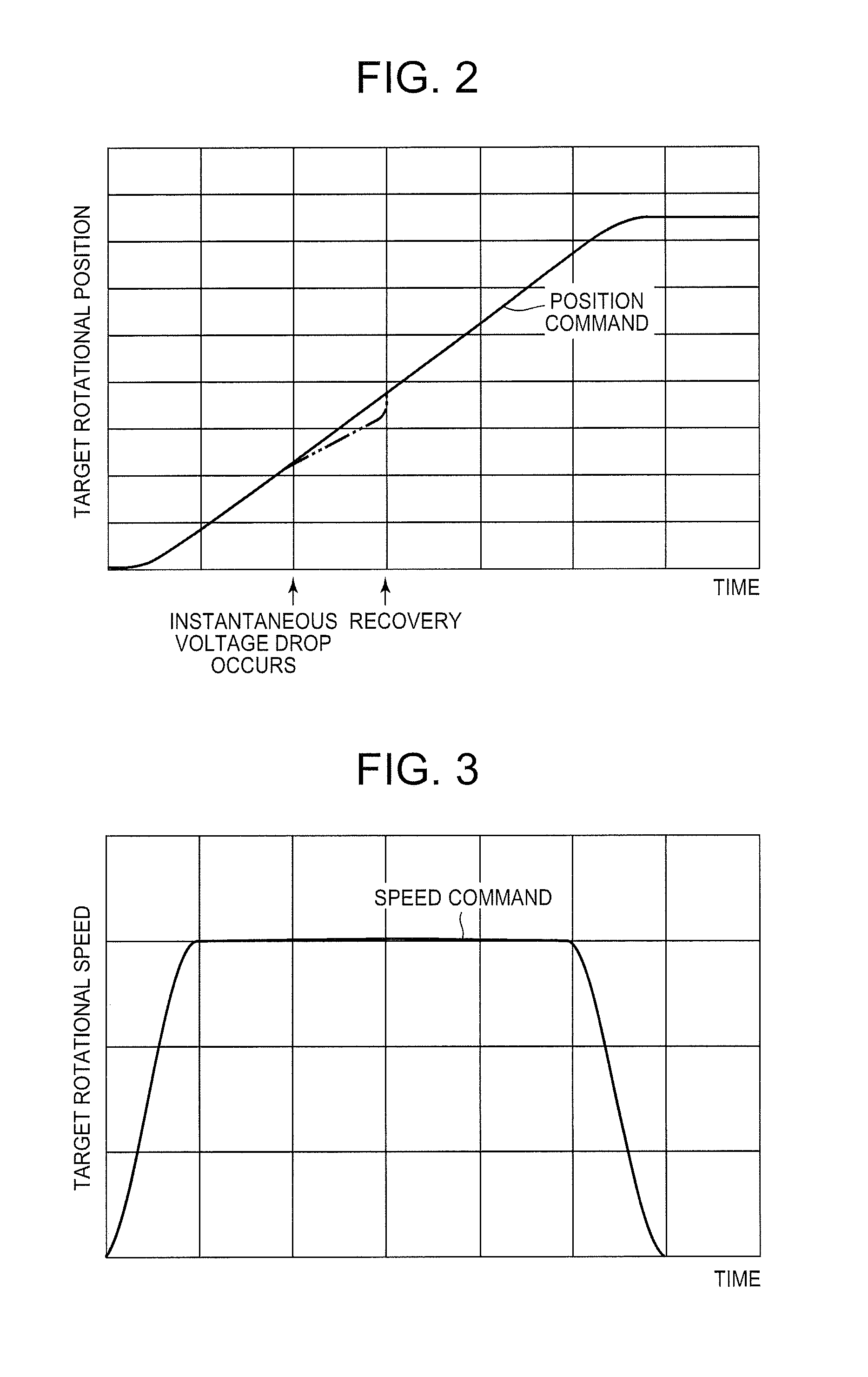
[0082]As described above, in this embodiment, once an instantaneous voltage drop is detected by the voltage fluctuation detection unit 110, the position control unit 110 limits the speed command to be output. Therefore, in this embodiment, the increase in the speed deviation to be output from the subtraction unit 111, which happens when an instantaneous voltage drop occurs, can be suppressed; thus, the increase in the value of the torque command which will be output from the speed control unit 112 can be suppressed. Therefore, in this embodiment, even when an instantaneous voltage drop occurs, the motor 102 can be properly controlled to have the robot perform desired operations, and also a windup phenomenon can be prevented from occurring to prevent the unstable behavior of the robot. Consequently, in this embodiment, even when an instantaneous voltage drop occurs, the position control unit 110 limits the speed command; therefore, after the instantane...

modification example 1

of Motor Control Method after Instantaneous Voltage Drop

[0089]In the above-described embodiment, when an instantaneous voltage drop ends and the voltage of the power source 103 is recovered above the reference value, the position control unit 110 cancels the limit on the speed command, and the position command output unit 108 returns the position command to the original state. Beside this, when the voltage of the power source 103 is recovered above the reference value, first the position command output unit 108 delays the position command (i.e., first the position command output unit 108 outputs the commanded position in which the target rotational position of the motor 102 is moved back by a predetermined amount) to reduce the position deviation to be output from the subtraction unit 109, then the position control unit 110 cancels the limit on the speed command and the position command output unit 108 returns the position command to the original state at the position after the posi...

modification example 2

of Motor Control Method after Instantaneous Voltage Drop

[0098]In the above-described embodiment, upon the end of the instantaneous voltage drop and the recovery of the voltage of the power source 103, the position control unit 110 cancels the limit on the speed command, and the position command output returns the position command to the original state. Beside this, even after the voltage of the power source 103 has recovered, the speed command may continually be limited and the position command may continually be varied to reduce the rotational speed of the motor 102; when the position deviation output from the subtraction unit 109 is minimized to some extent, the position control unit 110 may cancel the limit on the speed command and the position command output unit 108 may return the position command to the original state. In other words, after a predetermined period of time has passed after the voltage of the power source 103 recovered, the position control unit 110 may cancel th...


PUM


Abstract

The present invention provides a motor control device capable of operating a robot properly without stopping a motor that operates the robot even when an instantaneous voltage drop occurs. The motor control device 10 that controls the robot operating motor 102 is equipped with the subtraction unit 109 that calculates the position deviation for which the actual rotational position is subtracted from the position command, the position control unit 110 that converts the position deviation to the speed command, the subtraction unit 111 that calculates the speed deviation for which the actual rotational speed measurement is subtracted from the speed command, the speed control unit 112 that converts the speed deviation to a torque command, the limiter 113 that sets the maximum level of the torque command, the driver 114 that drives the motor 102, and the voltage fluctuation detection unit 115 that detects the voltage fluctuation of the power source 103; in the motor control device 101, when an instantaneous voltage drop is detected by the voltage fluctuation detection unit 115, the position command output unit 108 varies the position command so as to reduce the rotational speed of the motor 102, and the position control unit 110 limits the speed command to be output.

Description

FIELD OF INVENTION[0001]The present invention relates to a motor control device for controlling a motor that operates a robot. Also the present invention relates to a motor control method for controlling a motor that operates a robot. Further, the present invention relates to a control system that can be applied to a drive system and a rotation system such as a robot and a numerical control, and a location estimation method that is used in the control system.[0002]Conventionally known is a motor control device for controlling a DC motor (including a direct current motor, a DC brushless motor) that operates a robot (see Patent Reference 1, for example). In a motor control device described in Patent Reference 1, the rotational position of a motor is detected by a position detector, and the rotation speed of the motor is detected by a speed detector. Also, a subtractor calculates the position deviation [of the motor] by subtracting the output by the position detector from the position ...

Claims


Application Information

Patent Timeline
Patent Type & Authority Applications(United States)
IPC IPC(8): G05B19/19
CPCG05B19/19G05B2219/41142H02P7/06H02P29/02G05D3/20
Inventor OTSUJI, JUNITO, AKIHIROWATANABE, HIROKAZUODAGIRI, HIDEYUKI
Owner SANKYO SEIKI MFG CO LTD
Learn More