System for rearranging the counterweight of a crane operation

Active Publication Date: 2014-03-13
TADANO DEMAG GMBH
View PDF51 Cites 3 Cited by
  • Summary
  • Abstract
  • Description
  • Claims
  • Application Information

AI Technical Summary

Benefits of technology

The invention provides a system that allows a crane to have flexibility in its different modes of operation while also reducing the need for additional counterweights.

Problems solved by technology

That means that the founding structure is unmovable in respect to the base.

Method used


Image

  • System for rearranging the counterweight of a crane operation
  • System for rearranging the counterweight of a crane operation
  • System for rearranging the counterweight of a crane operation

Examples


Embodiment Construction

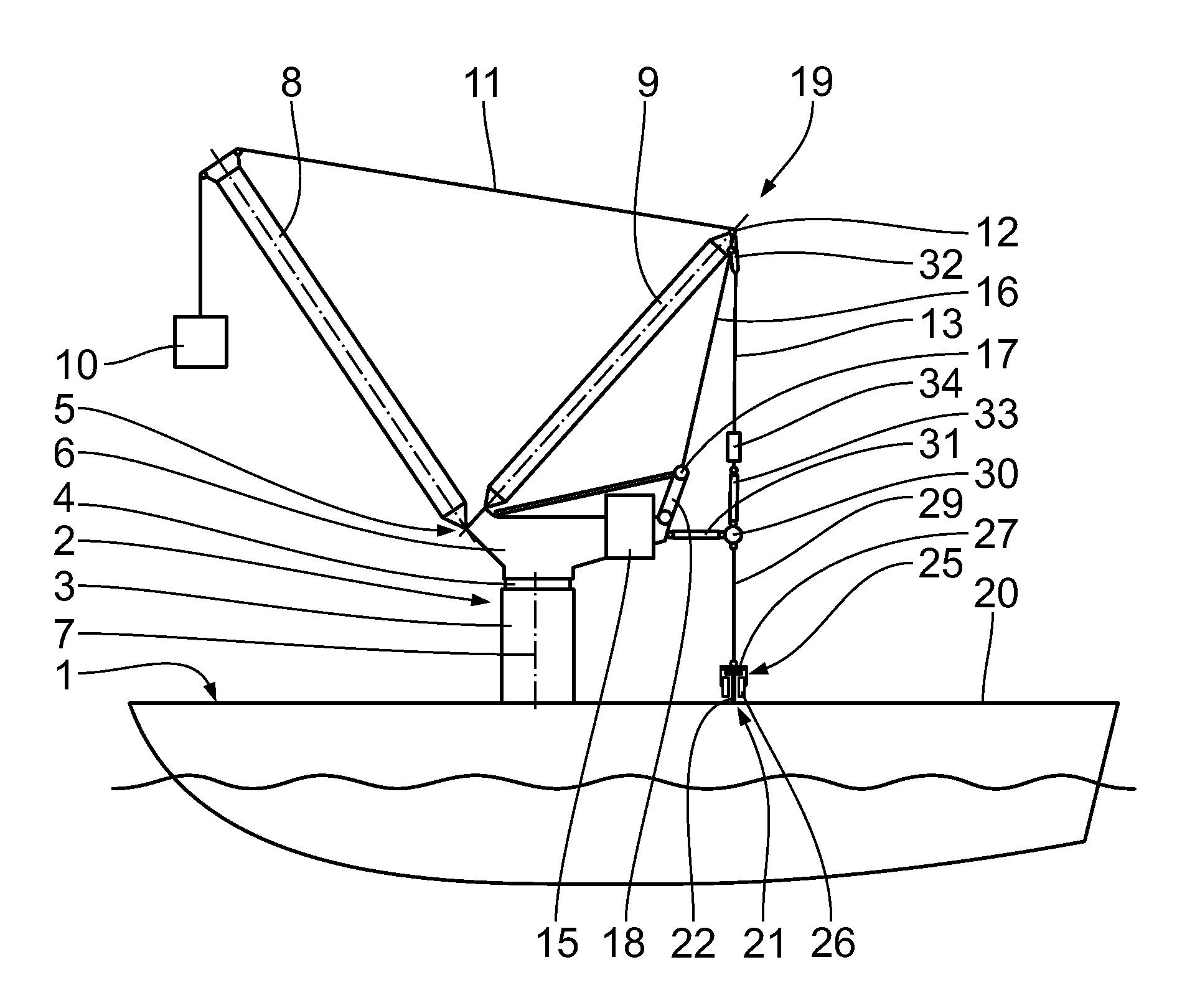
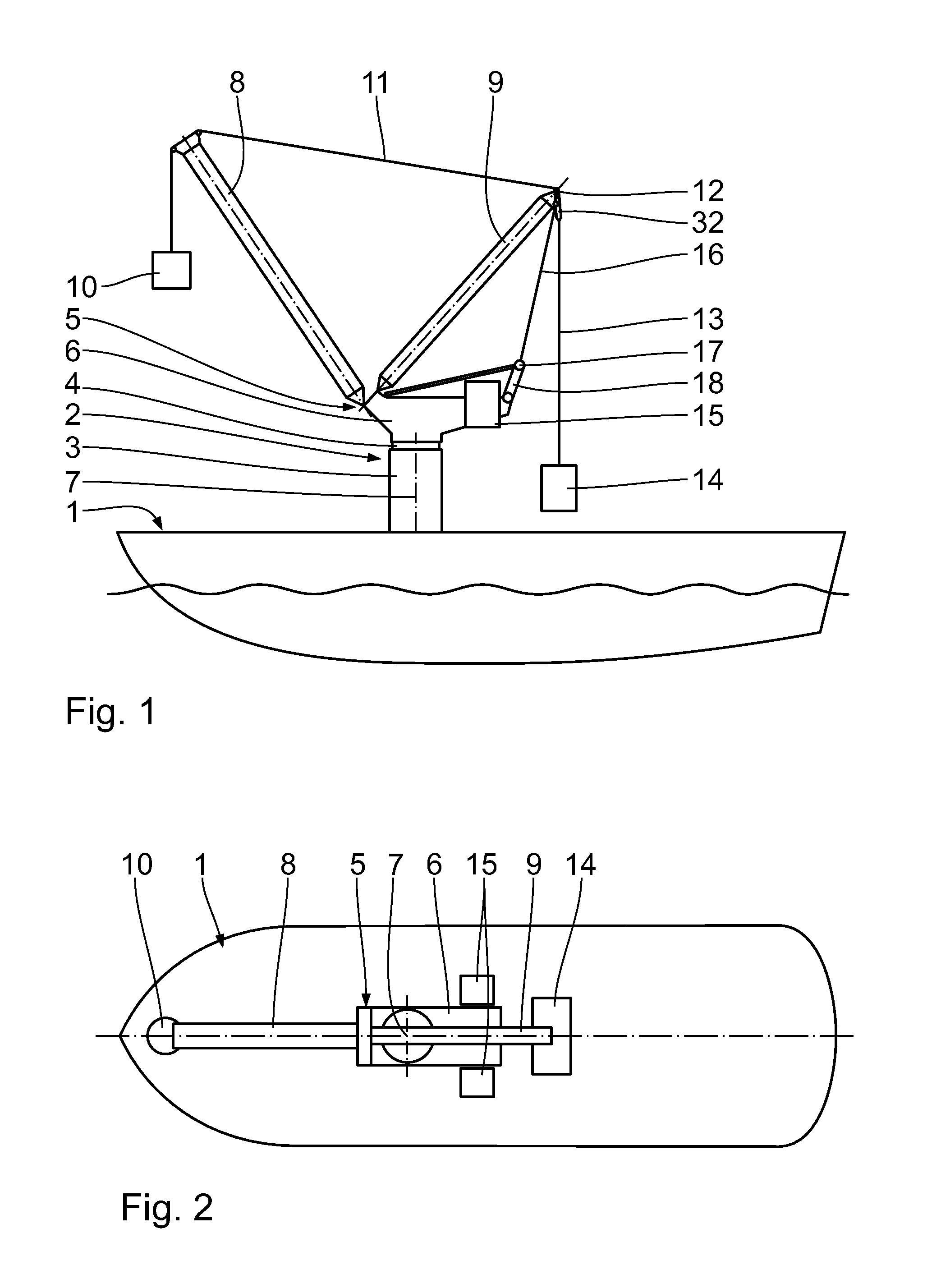
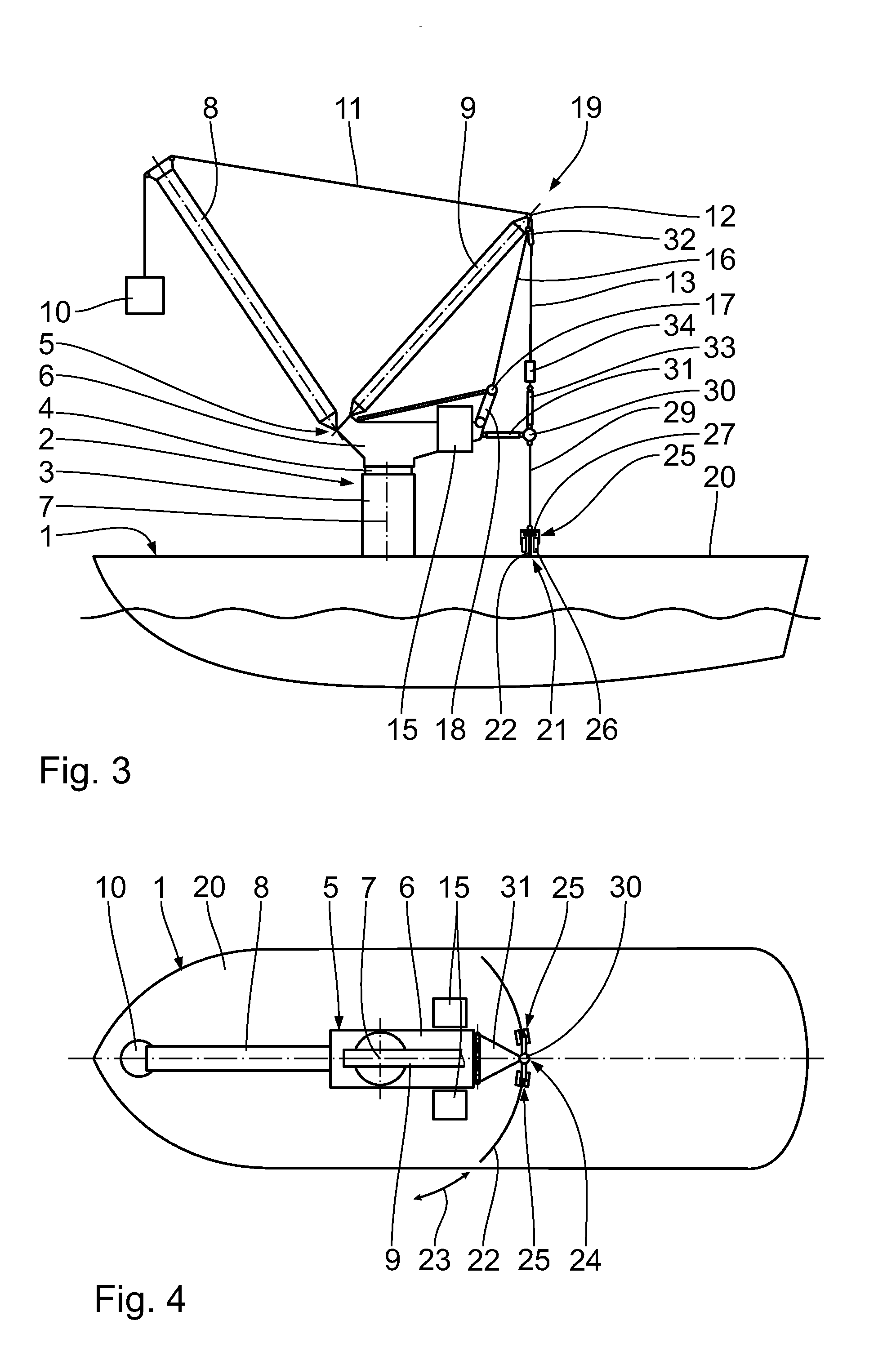
[0039]A vessel 1 according to FIGS. 3 to 5 comprises a system 19 according to the first embodiment of the invention. The system 19 enables the reduction of an amount of a counterweight of the crane 2. The founding structure 3 of the crane 2 is stationary disposed on a base 20. The base 20 is an upper deck of the vessel 1. The coupling unit 4 is a slewing ring and enables slewing of the superstructure 5 around the slewing axis 7 regarding the founding structure 3.

[0040]The base 20 is not part of the crane 2. In particular, it is also possible to provide the crane 2 on a stationary platform, e. g. of shore in the sea. It is further possible to provide the base on a barge or on a pontoon. It is also possible to provide the base 20 stationary on a flat roof of a large building.

[0041]The system 19 further comprises a suspension device 21 for suspending the crane 2 at the base 20. The suspension device 21 comprises a guiding structure 22 as a guiding track having a T-shaped guide rail. Th...


PUM


Abstract

A system (19; 19, 35) for reducing an amount of a counterweight for a crane comprises a crane (2) having a founding structure (3) being disposed on a base (20), a coupling unit (4), and a superstructure (5) being coupled to the founding structure (3) via the coupling unit (4). The system (19; 19, 35) further comprises a suspension device (21; 21, 36) for suspending the crane (2) at the base (20), said suspension device (21; 21, 36) having a guiding structure (22; 22, 37) defining a guiding direction (23; 23, 38), said guiding structure (22; 22, 37) being attached to the base (20), a displacement device (24) being displaceably attached to the guiding structure (22; 22, 37) along the guiding direction (23; 23, 38), and at least one suspension element (29) being connected with a first end to the crane (2) and being connected with a second end to the displacement device (24).

Description

FIELD OF THE INVENTION[0001]The invention relates to a system enabling a rearrangement of a counterweight assembly and configuration of such in a crane operation. Said system is in particular a system for reducing an amount of a counterweight for a crane, which needs to be catred for by the crane structure itself or by additional counterweight elements.BACKGROUND OF THE INVENTION[0002]U.S. Pat. No. 6,808,337 B1 discloses a maritime vessel with a stationary crane mounted thereon. The crane comprises a counterweight in order to counterbalance external and internal moments resulting from a load moment and to prevent tipping of the crane. A maritime vessel 1 according to the prior art is illustrated in FIG. 1, 2. A crane 2 is provided stationary on the vessel 1. The crane 2 comprises a founding structure 3 as a tower structure, a coupling unit 4 as a slewing ring and a superstructure 5 which is coupled to the founding structure 3 utilizing the coupling unit 4. The superstructure 5 compr...

Claims


Application Information

Patent Timeline
IPC IPC(8): B66C23/53B66C23/76
CPCB66C23/52B66C23/74
Inventor KARP, GUENTERHELWES, THORSTENSCHNEIDER, HANS
Owner TADANO DEMAG GMBH
Why Eureka
Try Eureka