
Image forming apparatus

a technology of image formation and forming unit, which is applied in the direction of electrographic process apparatus, instruments, optics, etc., can solve the problems of erroneously insertion of the image formation unit, affecting the replacement operation of the photoreceptor,

Inactive Publication Date: 2014-03-06
RICOH KK
View PDF10 Cites 16 Cited by
  • Summary
  • Abstract
  • Description
  • Claims
  • Application Information

AI Technical Summary

Benefits of technology

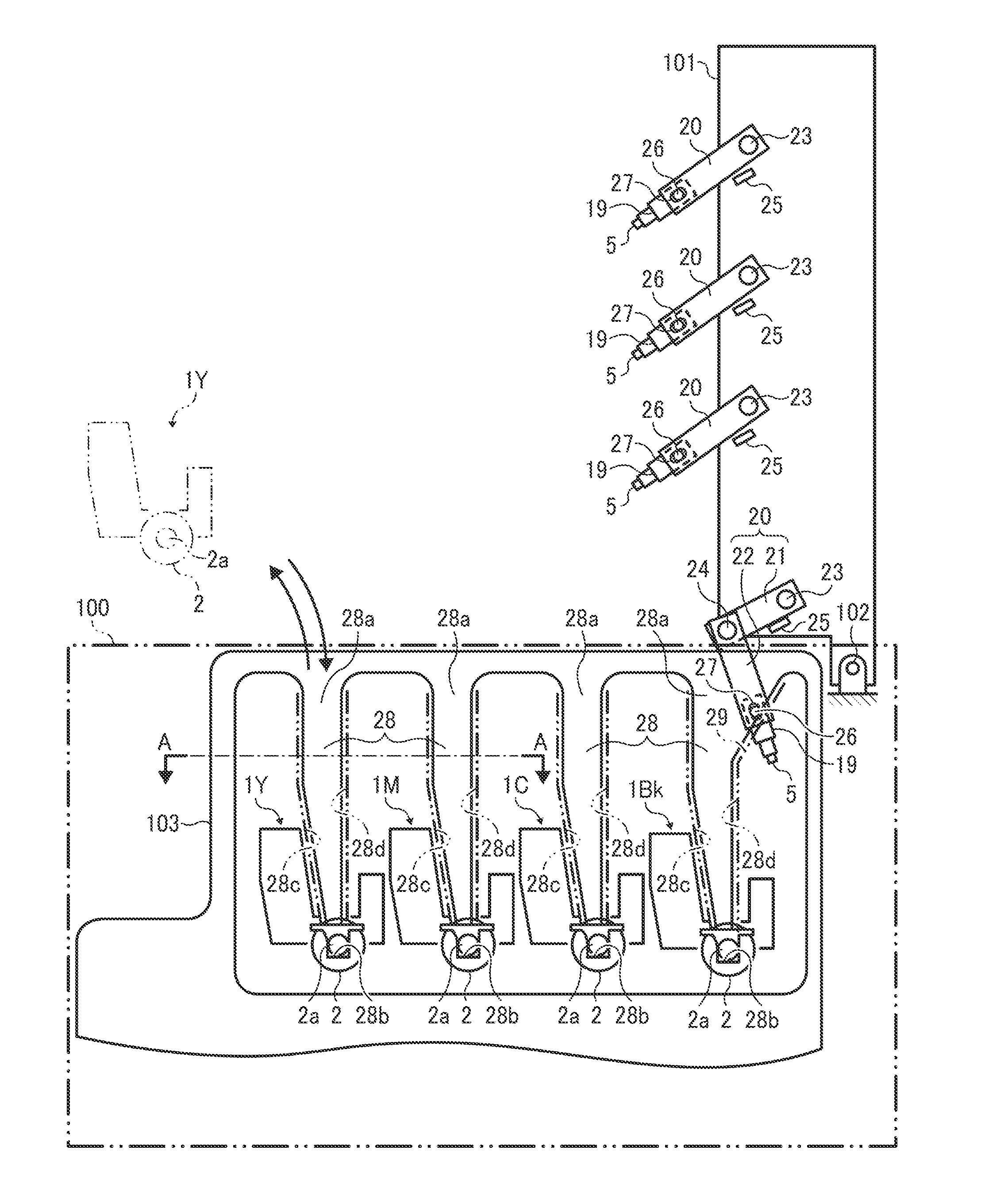
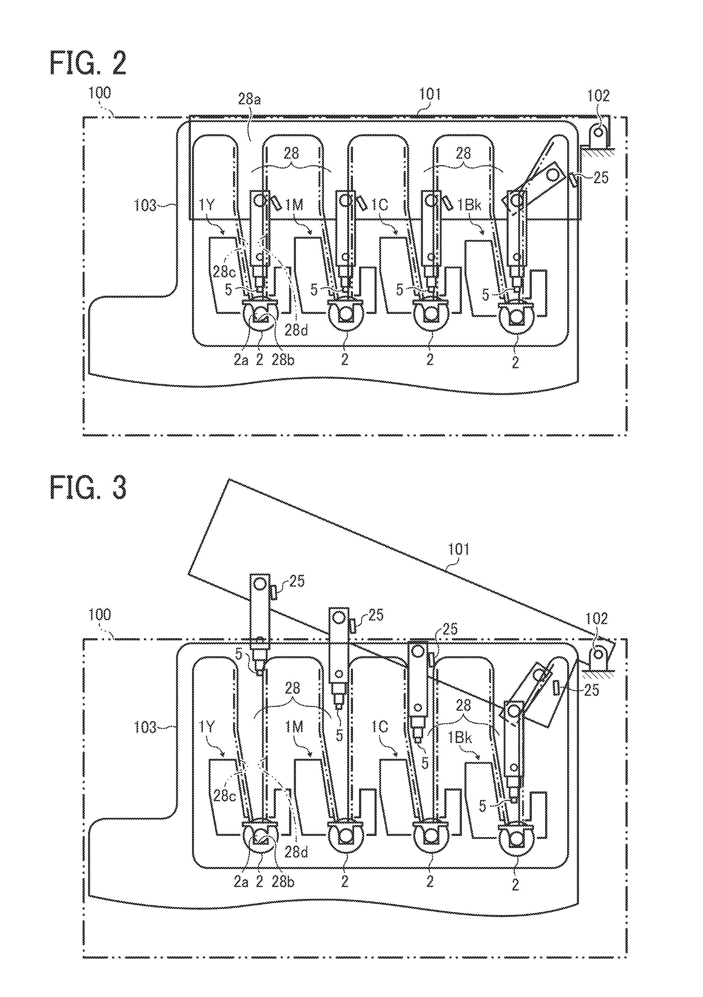
The invention is an improved image forming apparatus that prevents mistaken installation of the image formation unit. It includes a body, an image carrier, an exposure device, and a guide member to guide the exposure device to an exposure position. The image carrier is designed to form a latent image on its surface and is retractable from the exposure position. The image formation unit is detachable from the apparatus body. The guide member is used to guide both the image formation unit and the exposure device to the exposure position.

Problems solved by technology

Because the LED head is provided near the photoreceptor, if the photoreceptor or parts around the photoreceptor need to be replaced, the LED head will hinder the replacement operation of the photoreceptor.
However, because the guide groove to guide the LED head is disposed separately from a guide groove to attach and detach an image formation unit including the photoreceptor, there is a risk that the image formation unit is erroneously inserted into the guide groove for the LED head when the image formation unit is attached.

Method used


Image

  • Image forming apparatus
  • Image forming apparatus
  • Image forming apparatus

Examples


Embodiment Construction

[0019]Hereinafter, the present invention will be described referring to the accompanying drawings. In each figure illustrating an embodiment of the present invention, parts or component having the same function or shape are given the same reference numerals, and once explained, a redundant description thereof will be omitted.

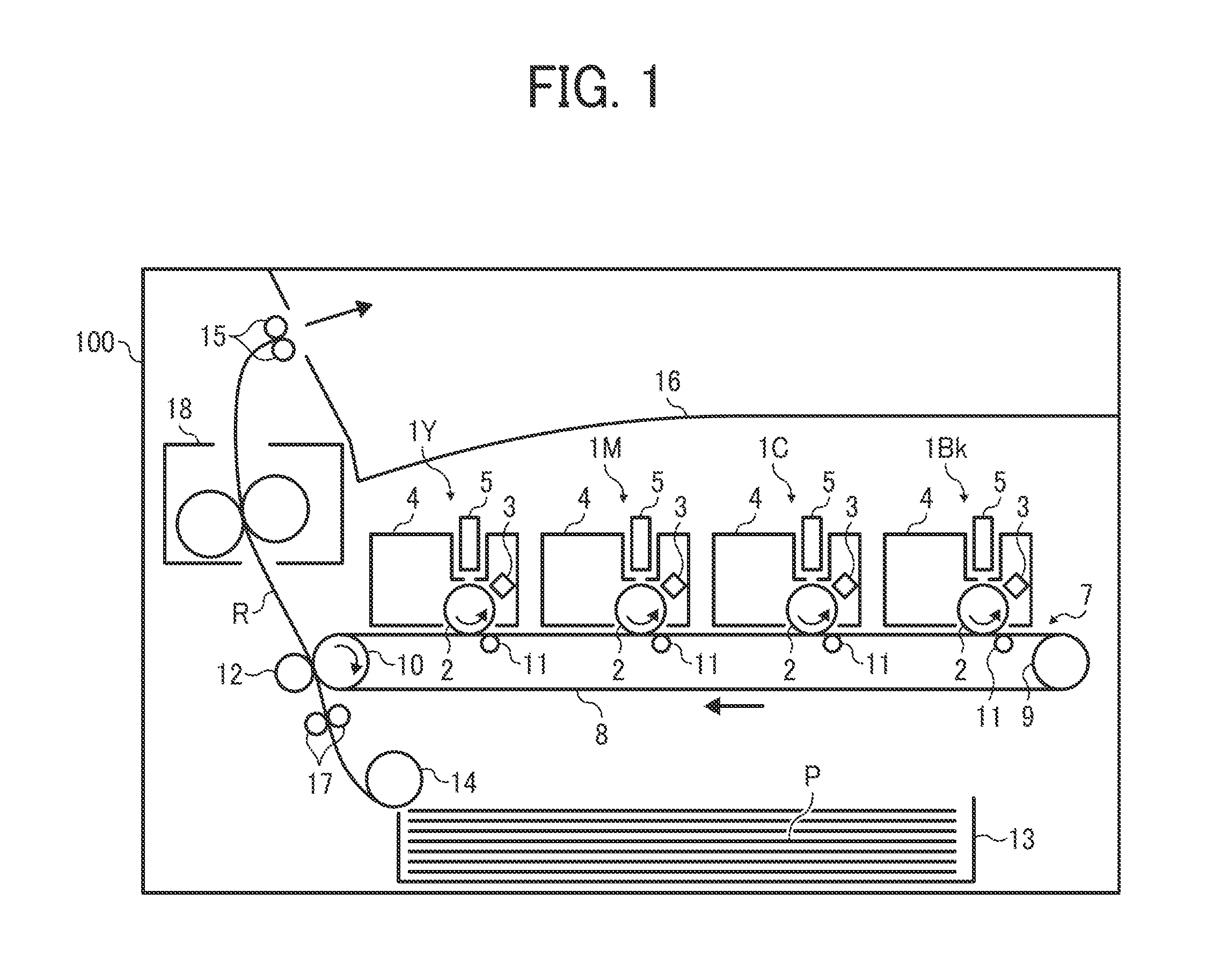
[0020]FIG. 1 shows a schematic configuration of a color laser printer as an image forming apparatus according to an embodiment of the present invention.

[0021]First, with reference to FIG. 1, basic operation of the printer according to an embodiment of the present invention will be described. It is to be noted, however, that the present invention is not limited to a printer but is applicable to monochrome printers, various types of copiers, facsimile machines, or multifunction apparatuses combining several of the functions of these devices.

[0022]As illustrated in FIG. 1, four processing units 1Y, 1M, 1C, and 1Bk each as an image formation unit are detachably atta...


PUM


Abstract

An image forming apparatus capable of preventing the image formation unit from being attached to a guide member for the image formation unit mistakenly, including an apparatus body; an image carrier including a rotary shaft; an exposure device configured to form a latent image through exposure of a surface of the image carrier and retractable from an exposure position; an image formation unit disposed detachably from the apparatus body; and a guide member to guide the exposure device to the exposure position. In the optimal apparatus, the guide member is used both to guide the image formation unit to the apparatus body and to guide the exposure device to the exposure position.

Description

CROSS-REFERENCE TO RELATED APPLICATION[0001]The present application claims priority pursuant to 35 U.S.C. §119 from Japanese patent application number 2012-188952, filed on Aug. 29, 2012, the entire disclosure of which is incorporated by reference herein.BACKGROUND[0002]1. Technical Field[0003]The present invention relates to an image forming apparatus such as a copier, a printer, a facsimile machine, or a multi-function apparatus having one or more capabilities of the above devices.[0004]2. Related Art[0005]In an image forming apparatus employing an electrophotographic method, provision of an LED head in which light-emitting diodes are aligned is used as one type of exposure approach to form a latent image by emitting light onto a photoreceptor. Because the LED head is provided near the photoreceptor, if the photoreceptor or parts around the photoreceptor need to be replaced, the LED head will hinder the replacement operation of the photoreceptor.[0006]Conceivably, replaceability c...

Claims


Application Information

Patent Timeline
Patent Type & Authority Applications(United States)
IPC IPC(8): G03G15/00
CPCG03G21/1666G03G21/1633G03G21/1671G03G21/1853
Inventor HASHIMOTO, HARUOTADA, KAORUNAKAMURA, KENJI
Owner RICOH KK
Learn More